Tools and Techniques for Musicians, Composers, and Tinkerers
[SOLVED]Audio codec shield with Arduino Due
116 posts · 224351 views
by youthreewire » Wed Jun 10, 2015 03:08 UTC
Hello,
I am working with the audio codec shield. I want to port the library to Arduino Due.Could some one please guide me how to do it? After Due I want to port it to Intel Edison and even pcDuino3.
Thanks
by guest » Wed Jun 10, 2015 03:45 UTC
the codecshield requires I2C and I2S interfaces. so locate those pins for your microcontroller platform. from what ive heard, the I2S drivers arent written yet for the edison. the codecshield is hardwired as an I2S slave device, so you will also need a timer/counter clock input pin available. there are ways around this, but it involves modifying the PCB of the codecshield. the basic program flow is as follows:
1. set up registers via I2C
2. count clock cycles from codecshield
3. interrupt every N clock cycles to initiate an I2S data transfer
by youthreewire » Wed Jun 10, 2015 04:06 UTC
I want to get this working first with the Due. I know that the I2C and SPI pins wont match the codec shield. So I have to manually wire it but is it possible to make the Library without using AVR specific code for the Due? I checked the library there is some ASM code and Timer specific code.So we have to change that and the rest is standard wire.h commands.
by youthreewire » Wed Jun 10, 2015 04:08 UTC
I tried running this on a Diecimilia and Maple but I want to stream the linein values over the serial port but the code appears to be crashing. Why can I not use Serial.print( ) functions with this library.Can the serial port issue be solved using a powerful microcontroller like the Due?
by youthreewire » Wed Jun 10, 2015 04:14 UTC
Here is the Due timer library
https://github.com/ivanseidel/DueTimer
AVR specific assembly code which needs to be changed
static inline void AudioCodecMega_data(int* _lin, int* _rin, int _lout, int _rout) {
  int _out_temp = _lout;
  PORTB |= (1<<PORTB0);  // toggle ss pina
  asm volatile ("out %0, %B1" : : "I" (_SFR_IO_ADDR(SPDR)), "r" (_out_temp) );
  PORTB &= ~(1<<PORTB0); // toggle ss pin
  while(!(SPSR & (1<<SPIF))){ // wait for data transfer to complete
  }
  asm volatile ("out %0, %A1" : : "I" (_SFR_IO_ADDR(SPDR)), "r" (_out_temp) );
  asm volatile ("in r3, %0" : : "I" (_SFR_IO_ADDR(SPDR)) );
  _out_temp = _rout;
  while(!(SPSR & (1<<SPIF))){ // wait for data transfer to complete
  }
  asm volatile ("out %0, %B1" : : "I" (_SFR_IO_ADDR(SPDR)), "r" (_out_temp) );
  asm volatile ("in r2, %0" : : "I" (_SFR_IO_ADDR(SPDR)) );
  asm volatile ("movw %0, r2" : "=r" (*_lin) : );
  while(!(SPSR & (1<<SPIF))){ // wait for data transfer to complete
  }
  asm volatile ("out %0, %A1" : : "I" (_SFR_IO_ADDR(SPDR)), "r" (_out_temp) );
  asm volatile ("in r3, %0" : : "I" (_SFR_IO_ADDR(SPDR)) );
  while(!(SPSR & (1<<SPIF))){ // wait for data transfer to complete
  }
  asm volatile ("in r2, %0" : : "I" (_SFR_IO_ADDR(SPDR)) );
  asm volatile ("movw %0, r2" : "=r" (*_rin) : );
}
More AVR specific code
#elif ADCS == 1
  static inline void AudioCodecMega_ADC(unsigned int* _mod0value) {
    if (ADCSRA & (1 << ADIF)) { // check if sample ready
      _mod0temp += ADCL; // fetch ADCL first to freeze sample
      _mod0temp += (ADCH << 8); // add to temp register
      ADCSRA = 0xf7; // reset the interrupt flag
      if (--_i == 0) { // check if enough samples have been averaged
        // add in hysteresis to remove jitter
        if (((_mod0temp - *_mod0value) < HYST) || ((*_mod0value - _mod0temp) < HYST)) {
        }
        else {
          *_mod0value = _mod0temp; // move temp value
	}
        _mod0temp = 0x0000; // reset temp value
        _i = 64; // reset counter
      }
    }
  }
#elif ADCS == 2
  static inline void AudioCodecMega_ADC(unsigned int* _mod0value, unsigned int* _mod1value) {
    if (ADCSRA & (1 << ADIF)) { // check if sample ready
      --_i; // check which sample we are on
      if (_i == 129) { // do nothing, first sample after mux change
      }
      else if (_i >= 65) { // sample ADC0
        _mod0temp += ADCL; // fetch ADCL first to freeze sample
        _mod0temp += (ADCH << 8); // add to temp register
        if (_i == 65) { // check if enough samples have been averaged
          // add in hysteresis to remove jitter
          if (((_mod0temp - *_mod0value) < HYST) || ((*_mod0value - _mod0temp) < HYST)) {
          }
          else {
            *_mod0value = _mod0temp; // move temp value
	    }
          _mod0temp = 0x0000; // reset temp value
          ADMUX = 0x41; // switch to ADC1
        }
      }
      else if (_i < 64) { // sample ADC1, first sample (64) after mux change ignored
        _mod1temp += ADCL; // fetch ADCL first to freeze sample
        _mod1temp += (ADCH << 8); // add to temp register
        if (_i == 0) { // check if enough samples have been averaged
          // add in hysteresis to remove jitter
          if (((_mod1temp - *_mod1value) < HYST) || ((*_mod1value - _mod1temp) < HYST)) {
          }
          else {
            *_mod1value = _mod1temp; // move temp value
	    }
          _mod1temp = 0x0000; // reset temp value
          ADMUX = 0x40; // switch to ADC0
          _i = 130; // reset counter
        }
      }
      ADCSRA = 0xf7; // reset the interrupt flag
    }
  }
#endif
by youthreewire » Wed Jun 10, 2015 04:37 UTC
I found some sample code which compiles for Due. But I do not know how to implement the examples like "fixed_delay" in the provided library.
Sample code here:
#include <Wire.h>
#include <SPI.h>

#define LINVOL 23
#define RINVOL 23
#define LHPVOL 121
#define RHPVOL 121
#define ADCHPD 0
#define SIDEATT 0
#define SIDETONE 0
#define DACSEL 1
#define BYPASS 0
#define INSEL 0
#define MUTEMIC 1
#define MICBOOST 0
#define SAMPLE_RATE 44

volatile boolean l;

unsigned int temp = 0;
int temp_spi[4];

//TC1 ch 0
void TC3_Handler()
{
        TC_GetStatus(TC1, 0);

        temp = random(65535);
        temp_spi[0] = SPI.transfer(10,highByte(temp),SPI_CONTINUE);
        temp_spi[1] = SPI.transfer(10,lowByte(temp),SPI_CONTINUE);
        temp_spi[2] = SPI.transfer(10,highByte(temp),SPI_CONTINUE);
        temp_spi[3] = SPI.transfer(10,lowByte(temp),SPI_LAST);
        Serial.println(temp_spi[0]);
        Serial.println(temp_spi[1]);
        Serial.println(temp_spi[2]);
        Serial.println(temp_spi[3]);
}

void startTimer(Tc *tc, uint32_t channel, IRQn_Type irq, uint32_t frequency) {
        pmc_set_writeprotect(false);
        pmc_enable_periph_clk((uint32_t)irq);
        TC_Configure(tc, channel, TC_CMR_WAVE | TC_CMR_WAVSEL_UP_RC | TC_CMR_TCCLKS_TIMER_CLOCK4);
        uint32_t rc = VARIANT_MCK/128/frequency; //128 because we selected TIMER_CLOCK4 above
        TC_SetRA(tc, channel, rc/2); //50% high, 50% low
        TC_SetRC(tc, channel, rc);
        TC_Start(tc, channel);
        tc->TC_CHANNEL[channel].TC_IER=TC_IER_CPCS;
        tc->TC_CHANNEL[channel].TC_IDR=~TC_IER_CPCS;
        NVIC_EnableIRQ(irq);
}

void AudioCodec_init() {
        randomSeed(analogRead(0));
        SPI.begin(10);
        SPI.setBitOrder(MSBFIRST);
        SPI.setClockDivider(10,21); // select to ss pin 10, 4 MHz
        SPI.setDataMode(10,SPI_MODE0);

        // setup i2c pins and configure codec
        // the new Wire library has trouble with 0x00, so (uint8_t) is added
        // To change the Wire interface speed, go to:
        // <path_from_arduino>\hardware\arduino\sam\libraries\Wire\Wire.h
        // and change the parameters TWI_CLOCK, RECV_TIMEOUT and XMIT_TIMEOUT
        // to the desire frequency.
        int temp_wire1;
        int temp_wire2;

        Wire.begin();
        Wire.beginTransmission(0x1a);
        Wire.write(0x0c); // power reduction register
        Wire.write((uint8_t)0x00); // turn everything on
        temp_wire1 = Wire.endTransmission();

        Wire.beginTransmission(0x1a);
        Wire.write(0x0e); // digital data format
        Wire.write(0x03); // 16b SPI mode
        temp_wire2 = Wire.endTransmission();

        Serial.println(temp_wire1);
        Serial.println(temp_wire2);

        Wire.beginTransmission(0x1a);
        Wire.write((uint8_t)0x00); // left in setup register
        Wire.write((uint8_t)LINVOL);
        Wire.endTransmission();

        Wire.beginTransmission(0x1a);
        Wire.write(0x02); // right in setup register
        Wire.write((uint8_t)RINVOL);
        Wire.endTransmission();

        Wire.beginTransmission(0x1a);
        Wire.write(0x04); // left headphone out register
        Wire.write((uint8_t)LHPVOL);
        Wire.endTransmission();

        Wire.beginTransmission(0x1a);
        Wire.write(0x06); // right headphone out register
        Wire.write((uint8_t)RHPVOL);
        Wire.endTransmission();

        Wire.beginTransmission(0x1a);
        Wire.write(0x0a); // digital audio path configuration
        Wire.write((uint8_t)ADCHPD);
        Wire.endTransmission();

        Wire.beginTransmission(0x1a);
        Wire.write(0x08); // analog audio pathway configuration
        Wire.write((uint8_t)((SIDEATT << 6)|(SIDETONE << 5)|(DACSEL << 4)|(BYPASS << 3)|(INSEL << 2)|(MUTEMIC << 1)|(MICBOOST << 0)));
        Wire.endTransmission();

        Wire.beginTransmission(0x1a);
        Wire.write(0x10); // clock configuration
        #if SAMPLE_RATE == 88
          Wire.write(0xbc);
        #elif SAMPLE_RATE == 44
          Wire.write(0xa0);
        #elif SAMPLE_RATE == 22
          Wire.write(0xe0);
        #elif SAMPLE_RATE == 8
          Wire.write(0xac);
        #elif SAMPLE_RATE == 2
          Wire.write(0xce);
        #endif
        Wire.endTransmission();

        Wire.beginTransmission(0x1a);
        Wire.write(0x12); // codec enable
        Wire.write(0x01);
        Wire.endTransmission();

}

void setup(){

        Serial.begin(9600);
        AudioCodec_init();
        startTimer(TC1, 0, TC3_IRQn, 44100); //startTimer(TC1, 0, TC3_IRQn, 44100); //TC1 channel 0, the IRQ for that channel and the desired frequency
}

void loop(){
}
by youthreewire » Wed Jun 10, 2015 04:39 UTC
Looking at the code I think there are 12C(wire) and SPI pins being used. So what could be the connection diagram between the Due and the Shield?
by guest » Wed Jun 10, 2015 17:56 UTC
on the maple, USB conflicts with SPI data transfers, so it cant be used (it can be used, but causes glitches). you can transfer over serial on an UNO, but it requires your own code, as the serial library is not optimized for speed. if you are trying to transfer data, you will need:
16b/sample * 2 sample (stereo) * 44ksamples/second = 1.4Mbps
since there is overhead in serial, you will probably need at least 2Mbps to actually make it work.
awesome that you found code that works! and its doing it over the SPI as well (usually SPI ports will double as I2S ports, so it might be I2S on the low level). so if you want to implement different code, you keep the data transfer the same as they have it shown. your incoming data is:
left = (temp_spi[0] << 8) | temp_spi[1];
right = (temp_spi[2] << 8) | temp_spi[3];
so to do delay, you just make a buffer, and load those data in, and take the data out from a different address. the rest of the example code should stay the same.
by youthreewire » Thu Jun 11, 2015 04:39 UTC
Now I have two microcontrollers on that works at 16 Mhz works at 2.5Mbaud and other at 84Mhz but works only at 1Mbaud. So which one should I use here? But I am assuming the codec shield will work better with the 84Mhz device as it has more RAM .
by youthreewire » Thu Jun 11, 2015 10:37 UTC
I ran this code but it crashes .I cant get the serial port to work with this program.I put anything to print the program crashes. If I disable the timer function in the setup then it prints otherwise it crashes. Could some one help me out here.
by youthreewire » Thu Jun 11, 2015 14:16 UTC
So,What is left_in,left_out, right_in and right_out in this code? How do I manipulate these to just echo and playback with little delay like in the example fixed_delay etc. I could not understand when you wrote this
left = (temp_spi[0] << 8) | temp_spi[1];
right = (temp_spi[2] << 8) | temp_spi[3];
by guest » Thu Jun 11, 2015 18:21 UTC
left_in = (temp_spi[0] << 8) | temp_spi[1];
right_in = (temp_spi[2] << 8) | temp_spi[3];
temp = left_out;
temp1 = right_out;
temp_spi[0] = SPI.transfer(10,highByte(temp),SPI_CONTINUE);
temp_spi[1] = SPI.transfer(10,lowByte(temp),SPI_CONTINUE);
temp_spi[2] = SPI.transfer(10,highByte(temp1),SPI_CONTINUE);
temp_spi[3] = SPI.transfer(10,lowByte(temp1),SPI_LAST);
by youthreewire » Sat Jun 13, 2015 14:27 UTC
So what could be connection diagram for Due? I2C I know.
by guest » Sat Jun 13, 2015 18:58 UTC
i dont know much about the DUE, i dont own one and have never used one. if you find an I2S library for it, that will probably also have a connection diagram.
by youthreewire » Sun Jun 14, 2015 12:06 UTC
You mentioned this code left_in and right_in
left_in = (temp_spi[0] << 8) | temp_spi[1];
        right_in = (temp_spi[2] << 8) | temp_spi[3];
But where are we mapping left_out and right_out in the device? You just declared them as temp variables. Like in your library the audio_codec_init function takes all these four parameters but here how do we map it?
by youthreewire » Sun Jun 14, 2015 13:00 UTC
I want to convert this function.I understand the following code attempts to do what AudioCodecMega_data( does.
AudioCodecMega_data( function definition from official library:
static inline void AudioCodecMega_data(int* _lin, int* _rin, int _lout, int _rout) {
  int _out_temp = _lout;
  PORTB |= (1<<PORTB0);  // toggle ss pina
  asm volatile ("out %0, %B1" : : "I" (_SFR_IO_ADDR(SPDR)), "r" (_out_temp) );
  PORTB &= ~(1<<PORTB0); // toggle ss pin
  while(!(SPSR & (1<<SPIF))){ // wait for data transfer to complete
  }
  asm volatile ("out %0, %A1" : : "I" (_SFR_IO_ADDR(SPDR)), "r" (_out_temp) );
  asm volatile ("in r3, %0" : : "I" (_SFR_IO_ADDR(SPDR)) );
  _out_temp = _rout;
  while(!(SPSR & (1<<SPIF))){ // wait for data transfer to complete
  }
  asm volatile ("out %0, %B1" : : "I" (_SFR_IO_ADDR(SPDR)), "r" (_out_temp) );
  asm volatile ("in r2, %0" : : "I" (_SFR_IO_ADDR(SPDR)) );
  asm volatile ("movw %0, r2" : "=r" (*_lin) : );
  while(!(SPSR & (1<<SPIF))){ // wait for data transfer to complete
  }
  asm volatile ("out %0, %A1" : : "I" (_SFR_IO_ADDR(SPDR)), "r" (_out_temp) );
  asm volatile ("in r3, %0" : : "I" (_SFR_IO_ADDR(SPDR)) );
  while(!(SPSR & (1<<SPIF))){ // wait for data transfer to complete
  }
  asm volatile ("in r2, %0" : : "I" (_SFR_IO_ADDR(SPDR)) );
  asm volatile ("movw %0, r2" : "=r" (*_rin) : );
}
The code for Due which attempts to as the above code but no knowledge of _rout/right_ out and _lout/left_out
void TC3_Handler()
{
        TC_GetStatus(TC1, 0);

        temp = random(65535);
        temp1 = left_out;
        temp2 = right_out;

        temp_spi[0] = SPI.transfer(10,highByte(temp),SPI_CONTINUE);
        temp_spi[1] = SPI.transfer(10,lowByte(temp),SPI_CONTINUE);
        temp_spi[2] = SPI.transfer(10,highByte(temp),SPI_CONTINUE);
        temp_spi[3] = SPI.transfer(10,lowByte(temp),SPI_LAST);
        left_in = (temp_spi[0] << 8) | temp_spi[1];
        right_in = (temp_spi[2] << 8) | temp_spi[3];

}
by guest » Sun Jun 14, 2015 19:32 UTC
_rout is only needed because the code is in the library, otherwise just declaring your variable right_out is enough.
the very first hit on google for "arduino due i2s library" gave me this:
https://github.com/delsauce/ArduinoDueHiFi (which is linked from the arduino website itself as the reccomended i2s library, so it probably works)
if you are going to spend a bunch of time getting a library to work with the codec shield, you might as well have a good starting point.
by youthreewire » Mon Jun 15, 2015 04:18 UTC
I have seen the I2S library and I wanted to mention the same but you already did. I think your code is straightforward. I have most of them ported but just the AudioCodecMega_data function has to be ported.I do not understand what you are trying to do in the assembly here.I found one more thread but incomplete here:
http://forum.arduino.cc/index.php?topic=267937.0
So left_out and right_out are used in the functions so how do I replicate it through here
void TC3_Handler()
{
        TC_GetStatus(TC1, 0);

        temp = random(65535);
        temp1 = left_out;
        temp2 = right_out;

        temp_spi[0] = SPI.transfer(10,highByte(temp),SPI_CONTINUE);
        temp_spi[1] = SPI.transfer(10,lowByte(temp),SPI_CONTINUE);
        temp_spi[2] = SPI.transfer(10,highByte(temp),SPI_CONTINUE);
        temp_spi[3] = SPI.transfer(10,lowByte(temp),SPI_LAST);
        left_in = (temp_spi[0] << 8) | temp_spi[1];
        right_in = (temp_spi[2] << 8) | temp_spi[3];

}
How will the codec know how to pipe out right_out and left_out?If we just declare them as variables it wont be sufficient. They are to be written to some registers of the WM8731.
by youthreewire » Mon Jun 15, 2015 05:53 UTC
Also you are using Timer1 in the library and connected one pin SS to T1 in atmega328. In the mega library people changed it to Timer 5 and connected it to T5. Now as the per the new code for Due. TC1 and TC3 Handler are being used so which pin will correspond in functionality to T1 or T5.
by youthreewire » Mon Jun 15, 2015 06:38 UTC
guest wrote:left_in = (temp_spi[0] << 8) | temp_spi[1];
right_in = (temp_spi[2] << 8) | temp_spi[3];
temp = left_out;
temp1 = right_out;
temp_spi[0] = SPI.transfer(10,highByte(temp),SPI_CONTINUE);
temp_spi[1] = SPI.transfer(10,lowByte(temp),SPI_CONTINUE);
temp_spi[2] = SPI.transfer(10,highByte(temp1),SPI_CONTINUE);
temp_spi[3] = SPI.transfer(10,lowByte(temp1),SPI_LAST);
Could you tell me more clearly as to how the left_in is being mapped to left_out. Because WM8731 should also know how to set its output. Dont you think we have to use SPI to write the output out as well.
by youthreewire » Mon Jun 15, 2015 09:46 UTC
I set BYPASS=1 and it is working ,so we know that I2C is working but SPI(I2S) is not working for some reason.As you told me I wrote the code for SPI as this
void TC3_Handler()
{
        TC_GetStatus(TC1, 0);

        temp = random(65535);
        temp = left_out;
        temp1 = right_out;
        temp_spi[0] = SPI.transfer(10,highByte(temp),SPI_CONTINUE);
        temp_spi[1] = SPI.transfer(10,lowByte(temp),SPI_CONTINUE);
        temp_spi[2] = SPI.transfer(10,highByte(temp1),SPI_CONTINUE);
        temp_spi[3] = SPI.transfer(10,lowByte(temp1),SPI_LAST);
        left_in - (temp_spi[0]<<8)|temp_spi[1];
        right_in = (temp_spi[2]<<8)|temp_spi[3];
}
So what am I doing wrong here.Also I could not use TIMER pin because I do not know to what GPIO pin it corresponds to.
by guest » Mon Jun 15, 2015 19:50 UTC
awesome to hear that the i2c is working.
to use SPI (as compared to I2S), the SS pin needs to be toggled right at the beginning for a very specific amount of time. for both the uno and maple libraries, i had to hand tweak those parameters in assembly to get it right. i also had to use an oscilloscope to see what was happening. so, if you have an oscilloscope, you might be able to do this. but, this is not required for I2S, which i why i reccomend going that route.
also, the timer needs to be set up to count the number of pulses on the input pin. it looks like it is only setup to make a frequency in your code (44100).
by youthreewire » Wed Jun 17, 2015 10:21 UTC
I saw one fundamental difference.For atmega328 and atmega2560 the SPI_CLK_DIV was set to 2 which was putting it at 8Mhz but the function for Due was setting it to 4 Mhz.I will change this back to 8 mhz on the Due and check.
by youthreewire » Wed Jun 17, 2015 10:59 UTC
Now I am able to get the SPI values but the sound output is like a crackling buzz in the headphones. I think it could be that the clock of Due is 84Mhz and clock divider for SPI is not a whole number at 10 for 8 mhz SPI clock.It is 10.5. Now I will boost the frequency to 96 and see if I get better values and the clock will be at 8mhz.
by guest » Wed Jun 17, 2015 17:59 UTC
SPI will not work unless you toggle the SS pin correctly. please read the datasheet for the WM8731:
http://wiki.openmusiclabs.com/wiki/Audi ... WM8731.pdf
page 35 - DSP mode, mode B.
by youthreewire » Thu Jun 18, 2015 11:06 UTC
I think at 10.5 SPI clock divder the SS pin (which is pin10 in my code) is not toggling at the right frequnecy.
by guest » Thu Jun 18, 2015 17:59 UTC
it has nothing to do with SPI clock frequency. in standard SPI, SS goes low for the entire duration of the transmit. as you can see in the datasheet, you need it to go high at the start of the transmission, and then go low one clock cycle later.
by youthreewire » Fri Jun 19, 2015 03:33 UTC
This is the waveform that I am getting on the SS pin.
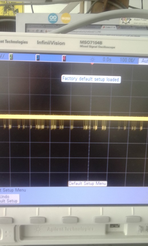
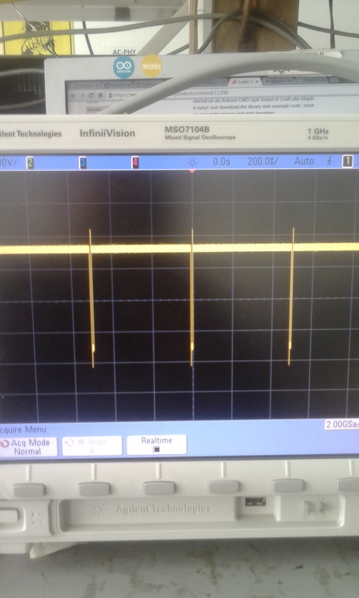
Oscilloscope Due pin 10 SS .by youthreewire » Fri Jun 19, 2015 04:18 UTC
The SS pin wave is at 13.5Khz. Sorry that was the wave duration not its frequcny.7.4Us is the pulse width.
by youthreewire » Fri Jun 19, 2015 04:22 UTC
I was also able to set the SS pin wave at 11.6Us (pulse width) when I changed the SPI clock to 4 Mhz. So what I observed is as I am changing the SPI clock divider the SS pin wave is also changing its frequency which is expected.I think I need to dig into the data sheet and see how SS pin is being toggled, at what frequency and all. So tell me one thing. In what SPI mode is the WM8731 chip being operated here .Is it a slave or a master? Because the Arduino library only works in master mode in which the WM8731 should be slave and receiving clock signals from the Arduino but if wm8731 is in master mode then it should be providing the clock signals to arduino (like the clock input pin T1 in Atmega328 or T5 in the Arduino mega) but the arduino cannot be in slave mode as the SPI library wont work for that. So can I put the WM8731 in slave mode. Please tell me what I have to set in the I2C to configure it initially in slave mode.
by guest » Sat Jun 20, 2015 05:21 UTC
the codecshield needs to be operated in slave mode, so it should work fine with the SPI on that account. note that your SS pin is always high, and only goes low during data transfer. if you look at the datasheet for the wm8731, this is the opposite of what you want. you might be better of using a different pin than the ss pin, and just generate your own ss signal in the interrupt.
by youthreewire » Sat Jun 20, 2015 07:55 UTC
The codec shield is the slave? But then what about the clock signal on pin T1 (on the atmega328 like arduinos).I think T1 is receiving the clock input from the codec shield. When I disconnected the pin it is not working.I think PIN T1 goes with the timer and accepts input from the WM8731 for clock. Please check the schematic and function of T1 pin in your code. You are using Timer 1 in your code and magically this implied that you were using the T1 pin and hardwiring it to clkout on the codec shield. I exactly did not understand the function of T1 pin.Could you explain more?
It is clear that the T1 pin is for external clock input timer interrupt. The data sheet of WM8731 says that if WM8731 is master it will send the clock signal.So one more doubt is is this clock signal on CLKOUT is what they are referring to or is it SCK clock for SPI?
by guest » Sat Jun 20, 2015 17:49 UTC
there are 3 clock signals on the codecshield:
1. I2C clock
2. SPI clock
3. codec master clock
the microcontroller T1 recieves the codec master clock, which should then fire an interrupt to drive the SPI. so SPI on the codec is in slave mode, whereas the codec master clock is in master mode.
by youthreewire » Sun Jun 21, 2015 05:57 UTC
What is the value of CLKOUT. So is it absolutely necessary to get the timer interrupt from CLKOUT? And what is the frequency of master clock.I went through the data sheet but could not find it.
by youthreewire » Sun Jun 21, 2015 10:03 UTC
I found some information about the Due timers here:
https://github.com/ivanseidel/DueTimer
Here they mention about connecting an external clock but TCLK0 but also mentioned about I/O Lines TIOA0 ,TIOB0. i am confused here.
https://github.com/ivanseidel/DueTimer/blob/master/TimerCounter.mdby guest » Sun Jun 21, 2015 20:37 UTC
that code does not allow for external clocks as one of its options. i found this arduino forum link that might be of some help:
http://forum.arduino.cc/index.php?topic=311872.0
it doesnt look like there is a standard library for doing this yet. the due is quite new, and there isnt a lot of support for it yet.
by youthreewire » Mon Jun 22, 2015 05:04 UTC
I tried the sketch in the thread but I get no update in the print statement. Everything reads zero. The sketch does not detect the CLKOUT signal on pin30.
I even ran this code here:
http://www.at91.com/discussions/viewtopic.php/f,24/t,23968/p,45148.html
But external IRQs still read 0.
The CLKOUT signal is a 11Mhz signal. But in both the example codes above the input signal is either a 0.5Hz signal or a 3 hz signal on pin30.
by guest » Mon Jun 22, 2015 06:52 UTC
did you follow this instruction in the original thread:
Remove TC_CMR_BURST_XC2 from TC2UsingExternalClock.ino
this was the same problem the other thread mentions as well
by youthreewire » Mon Jun 22, 2015 09:02 UTC
Yes I did remove that. The CLKOUT signal is a 11Mhz signal. But in both the example codes above the input signal is either a 0.5Hz signal or a 3 hz signal on pin30. I also gave it a signal from pin13 (LED) blinking every second but still I get 0.
I wonder how your library worked for the atmega328 based arduinos. Because once we set interrupts on the external clock of 11Mhz hardly any time might be left for the main loop to run.I was still able to send data over serial port from the main loop using your library.
by youthreewire » Mon Jun 22, 2015 13:27 UTC
Here is the video of my test.
http://youtu.be/CA1SehE_l60
due with connections.jpg
#define TC2_CHANNEL_FOR_TCLK8 2  /* presumed to correspond to XC2 */

volatile int irqsServiced;
unsigned int status;
int upflag = 0;
bool ledon=0;
int oldmillis=0;
/****************************************************************/

void TC8_Handler()
{
	/* clear interrupt */
	status = TC_GetStatus(TC2, TC2_CHANNEL_FOR_TCLK8);
	irqsServiced++;
}


/****************************************************************/

void setup()
{
	Serial.begin(115200);
        pinMode(13,OUTPUT);
        pinMode(30,INPUT);
	/* "The user must configure the Power Management Controller before any access to the input line information." per 34.4.2 */
	pmc_enable_periph_clk(ID_TC8);
	/* "Using the PIO Controller requires the NVIC to be programmed first." per 34.4.3 */
	NVIC_EnableIRQ(TC8_IRQn);
	/* external clock is an input */
	PIO_Configure(PIOD, PIO_INPUT, PIO_PD9, 0);
	/* TCLK8 is the "B" peripheral */
	PIO_SetPeripheral(PIOD, PIO_PERIPH_B, PIO_ABSR_P9);

	/* use internal clock */
	TC_Configure(TC2, TC2_CHANNEL_FOR_TCLK8,
				 (TC_CMR_TCCLKS_XC2 |
				  TC_CMR_EEVTEDG_RISING |
				  TC_CMR_EEVT_XC2 |
				  TC_CMR_ENETRG |
				  TC_CMR_WAVSEL_UP_RC |
				  TC_CMR_WAVE));
	/* load counter register */
	TC_SetRC(TC2, TC2_CHANNEL_FOR_TCLK8, 13);
	/* start the timer */
	TC_Start(TC2, TC2_CHANNEL_FOR_TCLK8);
	/* enable the timer-specific interrupts */
	REG_TC2_IER2 = TC_IER_CPCS;
}


/****************************************************************/

void loop()
{
	//delay(1000);
        if(upflag==0)
        {
        oldmillis = millis();
        upflag=1;
        }
        if((millis()-oldmillis)>=200)
        {
        ledon=!ledon;
        digitalWrite(13,ledon);
        upflag=0;
        }

	printf("irqsServiced: %d, status: %08x, CV2: %d\n", irqsServiced, status, REG_TC2_CV2);
	if (Serial.available() > 0)
	{
		char choice = Serial.read();
		if (choice == 'z')
		{
			REG_TC2_BCR = TC_BCR_SYNC;
		}
	}
}
by youthreewire » Mon Jun 22, 2015 14:56 UTC
Here is the output from another code:
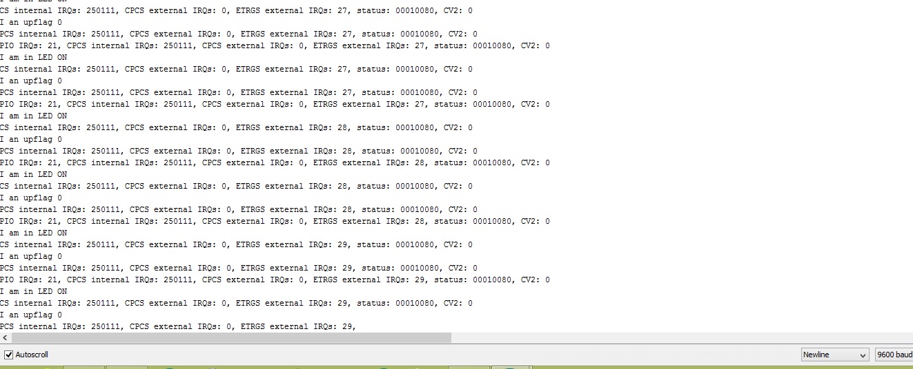
#define TC2_CHANNEL_FOR_TCLK8 2  /* presumed to correspond to XC2 */

enum Phase
   {
      TC2_INTERNAL,
      PIOD_EXTERNAL,
      TC2_EXTERNAL,
      DONE
   };

  /* enum Phase
   {
      TC2_EXTERNAL,
      TC2_EXTERNAL,
      TC2_EXTERNAL,
      DONE
   };*/

Phase phase;
int pioIRQsServiced;
int tc2IRQsServiced[3];
unsigned int status;
int upflag = 0;
bool ledon=0;
int oldmillis=0;

/****************************************************************/

void PIOD_Handler(void)
{
   /* clear interrupt */
   status = REG_PIOD_ISR;
   pioIRQsServiced++;
}


/****************************************************************/

void TC8_Handler()
{
   /* clear interrupt */
   status = TC_GetStatus(TC2, TC2_CHANNEL_FOR_TCLK8);
   if (status & TC_SR_CPCS)
   {
      if (phase == TC2_INTERNAL)
      {
         tc2IRQsServiced[0]++;
      }
      else
      {
         tc2IRQsServiced[1]++;
      }
   }
   if (status & TC_SR_ETRGS)
   {
      tc2IRQsServiced[2]++;
   }
}


/****************************************************************/

void SetupPIOD(void)
{
   int result;

   /* power on PIO ("Parallel Input/Output Controller") controller D */
   pmc_enable_periph_clk(ID_PIOD);
   /* enable interrupts for PIOD */
   NVIC_EnableIRQ(PIOD_IRQn);
   /* configure PD9 as general-purpose IO pin as opposed to the TCLK8 peripheral */
   result = PIO_Configure(PIOD, PIO_INPUT, PIO_PD9, PIO_IT_RISE_EDGE);
   printf("%d <- PIO_Configure\n", result);
   /* ensure we're interrupting on the rising edge of the external clock */
   REG_PIOD_AIMER = PIO_PD9;
   REG_PIOD_ESR = PIO_PD9;
   REG_PIOD_REHLSR = PIO_PD9;
   /* enable interrupts */
   REG_PIOD_IER = PIO_PD9;
}


/****************************************************************/

void TakeDownPIOD(void)
{
   TC_Stop(TC2, TC2_CHANNEL_FOR_TCLK8);
   TC_SetRC(TC2, TC2_CHANNEL_FOR_TCLK8, 0);
   REG_PIOD_IDR = PIO_PD9;
   NVIC_DisableIRQ(TC8_IRQn);
   pmc_disable_periph_clk(ID_PIOD);
}


/****************************************************************/

void SetupTC2(bool useInternalClock)
{
   int result;

   /* "The user must configure the Power Management Controller before any access to the input line information." per 34.4.2 */
   pmc_enable_periph_clk(ID_TC8);
   /* "Using the PIO Controller requires the NVIC to be programmed first." per 34.4.3 */
   NVIC_EnableIRQ(TC8_IRQn);
   result = PIO_Configure(PIOD, PIO_PERIPH_B, PIO_ABSR_P9, PIO_DEFAULT);
   printf("%d <- PIO_Configure\n", result);
   if (useInternalClock)
   {
      TC_Configure(TC2,
                TC2_CHANNEL_FOR_TCLK8,
                TC_CMR_TCCLKS_TIMER_CLOCK4 | TC_CMR_WAVSEL_UP_RC | TC_CMR_WAVE);
   }
   else
   {
      TC_Configure(TC2,
                TC2_CHANNEL_FOR_TCLK8,
                (TC_CMR_TCCLKS_XC2 |
                 TC_CMR_EEVTEDG_RISING |
                 TC_CMR_EEVT_XC2 |
                 TC_CMR_ENETRG |
                 TC_CMR_WAVSEL_UP_RC |
                 TC_CMR_WAVE));
   }
   /* load counter register */
   TC_SetRC(TC2, TC2_CHANNEL_FOR_TCLK8, 13);
   /* start the timer */
   TC_Start(TC2, TC2_CHANNEL_FOR_TCLK8);
   /* enable the timer-specific interrupts */
   REG_TC2_IER2 = TC_IER_CPCS | TC_IER_ETRGS;
}


/****************************************************************/

void TakeDownTC2(void)
{
   TC_Stop(TC2, TC2_CHANNEL_FOR_TCLK8);
   TC_SetRC(TC2, TC2_CHANNEL_FOR_TCLK8, 0);
   REG_TC2_IDR2 = TC_IER_CPCS | TC_IER_ETRGS;
   NVIC_DisableIRQ(TC8_IRQn);
   pmc_disable_periph_clk(ID_TC8);
}


/****************************************************************/

void setup(void)
{
   pinMode(13,OUTPUT);
   Serial.begin(9600);
   printf("start with TC2 internal\n");
   SetupTC2(true);
}


/****************************************************************/

void loop(void)
{

        if(upflag==0)
        {
        oldmillis = millis();
        upflag=1;
        Serial.println("I an upflag 0");
        }
        if((millis()-oldmillis)>=200)
        {
        ledon=!ledon;
        digitalWrite(13,ledon);
        upflag=0;
        Serial.println("I am in LED ON");
        }

  //phase=TC2_EXTERNAL;
  //Serial.println(phase);
   switch (phase)
   {
      case TC2_INTERNAL:
         if (tc2IRQsServiced[0] > 250000)
         {
            phase = PIOD_EXTERNAL;
            TakeDownTC2();
            printf("PASSED\nswitch to PIOD\n");
            SetupPIOD();
         }
         break;
      case PIOD_EXTERNAL:
         if (pioIRQsServiced > 20)
         {
            phase = TC2_EXTERNAL;
            TakeDownTC2();
            printf("PASSED\nswitch to TC2 external\n");
            SetupTC2(false);
         }
         break;
      case TC2_EXTERNAL:
         if (tc2IRQsServiced[1] > 20)
         {
            printf("PASSED!!!\n");
            for ( ; ; );
         }
         break;
      default:
         break;
   }
   //delay(1000);
   printf("PIO IRQs: %d, CPCS internal IRQs: %d, CPCS external IRQs: %d, ETRGS external IRQs: %d, status: %08x, CV2: %d\n", pioIRQsServiced, tc2IRQsServiced[0], tc2IRQsServiced[1], tc2IRQsServiced[2], status, REG_TC2_CV2);
   if (Serial.available() > 0)
   {
      char choice = Serial.read();
      if (choice == 'z')
      {
         REG_TC2_BCR = TC_BCR_SYNC;
      }
   }
}
The problem is does not immediately recognize the interrupt.It reads zero for a minute and then it starts.
by youthreewire » Mon Jun 22, 2015 15:04 UTC
Just checked.It starts detection when enum=2 i.e phase 3 when it goes into TC2_External. Good news is that now we have a method to detect the external clocks. I wonder if it would capture such a high freq signal.
Serial.print statements were also not working when the ISR_NAKED was declared and with reti( ). We need to such an equivalent to the code here as well.
by guest » Mon Jun 22, 2015 18:01 UTC
change your Serial.begin(9600) to something much higher. try 115200, and if that doesnt work, try all the higher options (i dont know what bit rates the serial monitor can accept).
by guest » Mon Jun 22, 2015 18:04 UTC
another thing you can do for these tests, is not send data every interrupt. the data is overflowing in the transmit buffer. also, set the clock divider to 256, and make sure you are getting a 44.1k pulse at your new ss pin (toggle a pin within the interrupt routine).
by youthreewire » Tue Jun 23, 2015 04:52 UTC
So tell me what does ISR_NAKED do in your code and how should I write an equivalent of not including reti() in my code?
by guest » Tue Jun 23, 2015 05:28 UTC
you should NOT use ISR_NAKED. that will make anything the main{} loop fail. the UNO needed that to help save processing time, but with the DUE it wont be necessary, and will make things more difficult. as a result, you also do not need to use reti().
by youthreewire » Tue Jun 23, 2015 10:54 UTC
Right now I am not using ISR_NAKED. But what I observed is that if I give the 11Mhz CLKOUT Signal as the input to pin30 the main loop() does not run at all.What shall I do now?It runs for signals with 200ms time period.
by guest » Tue Jun 23, 2015 18:28 UTC
you are doing too much in the main loop, most likely. get rid of anything in the mian loop, and just toggle an external pin in the interrupt, so you can see that its working. watch this pin on your scope, and make sure its at the frequency you expect. then, you can slowly add things back to your main loop, one at a time, and see what makes it break. but, before doing that, you could also get SPI working. with the MAPLE (another ARM processor), i found that the USB peripheral had an interrupt that took too long, and conflicted with the SPI. hopefully that is not the case here.
by youthreewire » Sat Jun 27, 2015 04:59 UTC
The main loop is just a switch statement with print statement.I will do what you said i.e to toggle a pin and that will give us an idea. I will check it with a scope and get back.
by youthreewire » Sat Jul 04, 2015 04:45 UTC
I am turning a GPIO pin on and off with the interrupt coming from CLKOUT pin.I am getting a frequency of 142 Khz i.e 0.14Mhz on the GPIO pin where as the clock signal is at a frequency of 11.363 Mhz signal. What shall I do now?
by youthreewire » Sat Jul 04, 2015 08:30 UTC
I also used attachinterrupt function but it is still slow.I think I might need to use assembly code to make it run faster. I am still surprised that the arduino 328/atmega2560 is able to track a 11Mhz CLKOUT signal and still is able to communicate over serial port. Due as per it specs is far ahead that arduino/atmel 328 but still I dont get the desired performance when it comes to tracking an external clock signal for interrupts.
by youthreewire » Sat Jul 04, 2015 09:28 UTC
I check the effect on CLKOUT signal on the Mega arduino and the time period for a GPIO pin toggle on interrupt from CLKOUT is 3.7Khz. So I think Due should work as this interrupt based GPIO toggling is not the same frequency as CLKOUT frequency. Using Due I got a 76 Khz wave and 142Khz wave. I think at 3.7Khz there is enough time for the atmega328/atmega2560 to do serial communication.I think I might have to reduce the timer update to 3.7 khz on the Due and then serial communication might work. What do you say?
by youthreewire » Sat Jul 04, 2015 10:55 UTC
So I think the right question would is can we set a clock divider when using an external clock for timer interrupt.If I can set the divider and make the interrupt fall around a time period of 3.7Khz then I can do serial communication easily with the Due.
by youthreewire » Sat Jul 04, 2015 12:45 UTC
#define TC2_CHANNEL_FOR_TCLK8 2  /* presumed to correspond to XC2 */

enum Phase
   {
      TC2_INTERNAL,
      PIOD_EXTERNAL,
      TC2_EXTERNAL,
      DONE
   };

  /* enum Phase
   {
      TC2_EXTERNAL,
      TC2_EXTERNAL,
      TC2_EXTERNAL,
      DONE
   };*/

Phase phase;
int pioIRQsServiced;
int tc2IRQsServiced[3];
unsigned int status;
int upflag = 0;
bool ledon,ledon1=0;
int oldmillis=0;

/****************************************************************/

void PIOD_Handler(void)
{
   /* clear interrupt */
   status = REG_PIOD_ISR;
   pioIRQsServiced++;
}


/****************************************************************/

void TC8_Handler()
{
  ledon1= !(ledon1);
    digitalWrite(13,ledon1);
  /* clear interrupt */
   status = TC_GetStatus(TC2, TC2_CHANNEL_FOR_TCLK8);
   if (status & TC_SR_CPCS)
   {
      if (phase == TC2_INTERNAL)
      {
         tc2IRQsServiced[0]++;
      }
      else
      {
         tc2IRQsServiced[1]++;
      }
   }
   if (status & TC_SR_ETRGS)
   {
      tc2IRQsServiced[2]++;
   }
}


/****************************************************************/

void SetupPIOD(void)
{
   int result;

   /* power on PIO ("Parallel Input/Output Controller") controller D */
   pmc_enable_periph_clk(ID_PIOD);
   /* enable interrupts for PIOD */
   NVIC_EnableIRQ(PIOD_IRQn);
   /* configure PD9 as general-purpose IO pin as opposed to the TCLK8 peripheral */
   result = PIO_Configure(PIOD, PIO_INPUT, PIO_PD9, PIO_IT_RISE_EDGE);
   printf("%d <- PIO_Configure\n", result);
   /* ensure we're interrupting on the rising edge of the external clock */
   REG_PIOD_AIMER = PIO_PD9;
   REG_PIOD_ESR = PIO_PD9;
   REG_PIOD_REHLSR = PIO_PD9;
   /* enable interrupts */
   REG_PIOD_IER = PIO_PD9;
}


/****************************************************************/

void TakeDownPIOD(void)
{
   TC_Stop(TC2, TC2_CHANNEL_FOR_TCLK8);
   TC_SetRC(TC2, TC2_CHANNEL_FOR_TCLK8, 0);
   REG_PIOD_IDR = PIO_PD9;
   NVIC_DisableIRQ(TC8_IRQn);
   pmc_disable_periph_clk(ID_PIOD);
}


/****************************************************************/

void SetupTC2(bool useInternalClock)
{
   int result;

   /* "The user must configure the Power Management Controller before any access to the input line information." per 34.4.2 */
   pmc_enable_periph_clk(ID_TC8);
   /* "Using the PIO Controller requires the NVIC to be programmed first." per 34.4.3 */
   NVIC_EnableIRQ(TC8_IRQn);
   result = PIO_Configure(PIOD, PIO_PERIPH_B, PIO_ABSR_P9, PIO_DEFAULT);
   printf("%d <- PIO_Configure\n", result);
   if (useInternalClock)
   {
      TC_Configure(TC2,
                TC2_CHANNEL_FOR_TCLK8,
                TC_CMR_TCCLKS_TIMER_CLOCK4 | TC_CMR_WAVSEL_UP_RC | TC_CMR_WAVE);
   }
   else
   {
      TC_Configure(TC2,
                TC2_CHANNEL_FOR_TCLK8,
                (TC_CMR_TCCLKS_XC2 |
                 TC_CMR_EEVTEDG_RISING |
                 TC_CMR_EEVT_XC2 |
                 TC_CMR_ENETRG |
                 TC_CMR_WAVSEL_UP_RC |
                 TC_CMR_WAVE));
   }
   /* load counter register */
   TC_SetRC(TC2, TC2_CHANNEL_FOR_TCLK8, 13);
   /* start the timer */
   TC_Start(TC2, TC2_CHANNEL_FOR_TCLK8);
   /* enable the timer-specific interrupts */
   REG_TC2_IER2 = TC_IER_CPCS | TC_IER_ETRGS;
}


/****************************************************************/

void TakeDownTC2(void)
{
   TC_Stop(TC2, TC2_CHANNEL_FOR_TCLK8);
   TC_SetRC(TC2, TC2_CHANNEL_FOR_TCLK8, 0);
   REG_TC2_IDR2 = TC_IER_CPCS | TC_IER_ETRGS;
   NVIC_DisableIRQ(TC8_IRQn);
   pmc_disable_periph_clk(ID_TC8);
}


/****************************************************************/

void setup(void)
{
   pinMode(12,OUTPUT);
   pinMode(13,OUTPUT);
   Serial.begin(9600);
   printf("start with TC2 internal\n");
   SetupTC2(true);
}


/****************************************************************/

void loop(void)
{


  //phase=TC2_EXTERNAL;
  //Serial.println(phase);
   switch (phase)
   {
      case TC2_INTERNAL:
         if (tc2IRQsServiced[0] > 250000)
         {
            phase = PIOD_EXTERNAL;
            TakeDownTC2();
            printf("PASSED\nswitch to PIOD\n");
            SetupPIOD();
         }
         break;
      case PIOD_EXTERNAL:
         if (pioIRQsServiced > 20)
         {
            phase = TC2_EXTERNAL;
            TakeDownTC2();
            printf("PASSED\nswitch to TC2 external\n");
            SetupTC2(false);
         }
         break;
      case TC2_EXTERNAL:
         if (tc2IRQsServiced[1] > 20)
         {
            printf("PASSED!!!\n");
            for ( ; ; );
         }
         break;
      default:
         break;
   }
   //delay(1000);
   printf("PIO IRQs: %d, CPCS internal IRQs: %d, CPCS external IRQs: %d, ETRGS external IRQs: %d, status: %08x, CV2: %d\n", pioIRQsServiced, tc2IRQsServiced[0], tc2IRQsServiced[1], tc2IRQsServiced[2], status, REG_TC2_CV2);
   if (Serial.available() > 0)
   {
      char choice = Serial.read();
      if (choice == 'z')
      {
         REG_TC2_BCR = TC_BCR_SYNC;
      }
   }
}
code for toggle led on pin13 with external interrupt.I tried chaning TC_setRC and TC_setRA to change the width(timeperiod) of the signal but showed no effect.
by youthreewire » Sat Jul 04, 2015 13:07 UTC
In the latest test which I conducted over 30-40 iterations I am getting the timer period as 6us. So the frequency of the wave is 1000000/6 = 166khz. I think it is too high and not giving time for the serial comm in the main loop to finish.
I am able to set it to internal clock and vary the time period and frequency but I am not able to do so with the external clock signal given as timer interrupt..
by youthreewire » Sun Jul 05, 2015 06:12 UTC
uint32_t rc = (11111111/44100); //128 because we selected TIMER_CLOCK4 above
        //TC_SetRA(tc, channel, rc/2); //50% high, 50% low
        //TC_SetRC(tc, channel, rc);
        //TC_Start(tc, channel);

   TC_SetRA(TC2,TC2_CHANNEL_FOR_TCLK8,rc/2);
   TC_SetRC(TC2, TC2_CHANNEL_FOR_TCLK8,rc);
   /* start the timer */
   TC_Start(TC2, TC2_CHANNEL_FOR_TCLK8);
   /* enable the timer-specific interrupts */
   REG_TC2_IER2 = TC_IER_CPCS | TC_IER_ETRGS;
   TC2->TC_CHANNEL[TC2_CHANNEL_FOR_TCLK8].TC_IER=TC_IER_CPCS;
   TC2->TC_CHANNEL[TC2_CHANNEL_FOR_TCLK8].TC_IDR=~TC_IER_CPCS;
After adding these and adjusting SetRA and SetRC and rc I am able to see the interrupt toggling the LED and also able to communicate with serial port. I will put this again on the oscilloscope and check the time period and see if it falls around 3.7khz.But the interrupt counter becomes slow when in serial port comm but faster when it works alone.
by guest » Mon Jul 06, 2015 04:17 UTC
so, is TC_SetRA the clock divider? does the pin toggle at 11MHz/TC_SetRA? if you apply a slower clock to that pin (instead of the codecshield clock), does it reduce rate accordingly (this will verify that the counter is responding to the external clock, and not an internal one).
by youthreewire » Mon Jul 06, 2015 05:03 UTC
Even in Atmega328 or Arduino uno the pin does not toggle at 11Mhz. The ISR works at 3.7Khz. Now I did something new and I am able to toggle the LED at 3.67Khz.So I am hoping that it will work now.I had to set the baud at 1000000 bps and this changes the time period of the ISR toggle. Now I will invert the SS pin and see if I am able to read the sound data.
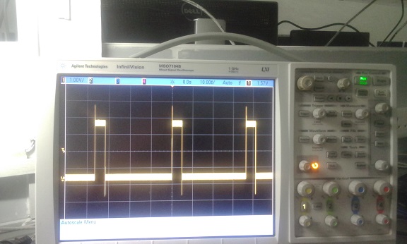
by youthreewire » Mon Jul 06, 2015 15:39 UTC
I just got SPI synced with external clock.
by guest » Mon Jul 06, 2015 16:10 UTC
glad to hear the SPI is now working. are you able to pass data?
also, the output rate should be ~11MHz/256 = 44.1kHz. i think the input clock is divided down to 5.6MHz, so the divide ratio is actually 128 to get a 44.1kHz interrupt rate.
also, digitalwrite() may be too slow for toggling the SS pin. if this ends up being the case, you should look into direct pin manipulation.
by youthreewire » Tue Jul 07, 2015 15:32 UTC
I am not able to get any data from the SPI. My first variable left_in was initialized to 30000 but now after SPI it gets written with 0, right_in remains the same as 30000(as to what it was initialized to when declaring it).So should I scope the MISO line? I am setting the clock like this
uint32_t rc = (11111111/44100); //128 because we selected TIMER_CLOCK4 above
        //TC_SetRA(tc, channel, rc/2); //50% high, 50% low
        //TC_SetRC(tc, channel, rc);
        //TC_Start(tc, channel);

   TC_SetRA(TC2,TC2_CHANNEL_FOR_TCLK8,rc/2);
   TC_SetRC(TC2, TC2_CHANNEL_FOR_TCLK8,rc);
   /* start the timer */
   TC_Start(TC2, TC2_CHANNEL_FOR_TCLK8);
   /* enable the timer-specific interrupts */
   REG_TC2_IER2 = TC_IER_CPCS | TC_IER_ETRGS;
   TC2->TC_CHANNEL[TC2_CHANNEL_FOR_TCLK8].TC_IER=TC_IER_CPCS;
   TC2->TC_CHANNEL[TC2_CHANNEL_FOR_TCLK8].TC_IDR=~TC_IER_CPCS;
And SPI like this:
SPI.begin(10);
        SPI.setBitOrder(MSBFIRST);
        SPI.setClockDivider(10,84); // select to ss pin 10, 4 MHz// favourable values 11,21,84
        SPI.setDataMode(10,SPI_MODE0);
by youthreewire » Wed Jul 08, 2015 05:19 UTC
I found the problem. The moment I put this function the ISR does not respond.
temp_spi[0] = SPI.transfer(10,highByte(temp),SPI_CONTINUE);
May be doing the transfer in the ISR is difficult, may be there isnt enough time for it. So how did you handle this in the maple?
Ranjan
by youthreewire » Wed Jul 08, 2015 05:24 UTC
Here is my code but the ISR gets stuck if I include SPI.transfer function in it.
include<SPI.h>
#include<Wire.h>
#define TC2_CHANNEL_FOR_TCLK8 2  /* presumed to correspond to XC2 */
#define LINVOL 23
#define RINVOL 23
#define LHPVOL 100
#define RHPVOL 100
#define ADCHPD 0
#define SIDEATT 0
#define SIDETONE 0
#define DACSEL 1
#define BYPASS 0
#define INSEL 0
#define MUTEMIC 1
#define MICBOOST 0
#define SAMPLE_RATE 44

volatile boolean l;

unsigned int temp = 0,temp1=0;
int temp_spi[4];
int m1[301],m2[301];
//TC1 ch 0
int left_out,right_out;
enum Phase
   {
      TC2_INTERNAL,
      PIOD_EXTERNAL,
      TC2_EXTERNAL,
      DONE
   };

  /* enum Phase
   {
      TC2_EXTERNAL,
      TC2_EXTERNAL,
      TC2_EXTERNAL,
      DONE
   };*/

Phase phase;
int pioIRQsServiced;
int tc2IRQsServiced[3];
unsigned int status;
int upflag = 0;
bool ledon,ledon1=0;
int oldmillis=0;
volatile int left_in=30000;
volatile int right_in=30000;

/****************************************************************/

void PIOD_Handler(void)
{
   /* clear interrupt */
   status = REG_PIOD_ISR;
   pioIRQsServiced++;
}


/****************************************************************/

void TC8_Handler()
{
  ledon1= !(ledon1);
    digitalWrite(13,ledon1);
  /* clear interrupt */
   status = TC_GetStatus(TC2, TC2_CHANNEL_FOR_TCLK8);
   if (status & TC_SR_CPCS)
   {
      if (phase == TC2_INTERNAL)
      {
         tc2IRQsServiced[0]++;
      }
      else
      {
         tc2IRQsServiced[1]++;
      }
   }
   if (status & TC_SR_ETRGS)
   {
      tc2IRQsServiced[2]++;
   }
    temp = random(65535);
        //temp = left_out;
        //temp1 = right_out;
        temp_spi[0] = SPI.transfer(10,highByte(temp),SPI_CONTINUE);
        temp_spi[1] = SPI.transfer(10,lowByte(temp),SPI_CONTINUE);
        temp_spi[2] = SPI.transfer(10,highByte(temp),SPI_CONTINUE);
        temp_spi[3] = SPI.transfer(10,lowByte(temp),SPI_LAST);
        left_in - (temp_spi[0]<<8)|temp_spi[1];
        right_in = (temp_spi[2]<<8)|temp_spi[3];

}


/****************************************************************/

void SetupPIOD(void)
{
   int result;

   /* power on PIO ("Parallel Input/Output Controller") controller D */
   pmc_enable_periph_clk(ID_PIOD);
   /* enable interrupts for PIOD */
   NVIC_EnableIRQ(PIOD_IRQn);
   /* configure PD9 as general-purpose IO pin as opposed to the TCLK8 peripheral */
   result = PIO_Configure(PIOD, PIO_INPUT, PIO_PD9, PIO_IT_RISE_EDGE);
   printf("%d <- PIO_Configure\n", result);
   /* ensure we're interrupting on the rising edge of the external clock */
   REG_PIOD_AIMER = PIO_PD9;
   REG_PIOD_ESR = PIO_PD9;
   REG_PIOD_REHLSR = PIO_PD9;
   /* enable interrupts */
   REG_PIOD_IER = PIO_PD9;
}


/****************************************************************/

void TakeDownPIOD(void)
{
   TC_Stop(TC2, TC2_CHANNEL_FOR_TCLK8);
   TC_SetRC(TC2, TC2_CHANNEL_FOR_TCLK8, 0);
   REG_PIOD_IDR = PIO_PD9;
   NVIC_DisableIRQ(TC8_IRQn);
   pmc_disable_periph_clk(ID_PIOD);
}


/****************************************************************/

void SetupTC2(bool useInternalClock)
{
   int result;

   /* "The user must configure the Power Management Controller before any access to the input line information." per 34.4.2 */
   pmc_enable_periph_clk(ID_TC8);
   /* "Using the PIO Controller requires the NVIC to be programmed first." per 34.4.3 */
   NVIC_EnableIRQ(TC8_IRQn);
   result = PIO_Configure(PIOD, PIO_PERIPH_B, PIO_ABSR_P9, PIO_DEFAULT);
   //printf("%d <- PIO_Configure\n", result);
   if (useInternalClock)
   {
      TC_Configure(TC2,
                TC2_CHANNEL_FOR_TCLK8,
                TC_CMR_TCCLKS_TIMER_CLOCK4 | TC_CMR_WAVSEL_UP_RC | TC_CMR_WAVE);
   }
   else
   {
      TC_Configure(TC2,
                TC2_CHANNEL_FOR_TCLK8,
                (TC_CMR_TCCLKS_XC2 |
                 TC_CMR_EEVTEDG_RISING |
                 TC_CMR_EEVT_XC2 |
                 TC_CMR_ENETRG |
                 TC_CMR_WAVSEL_UP_RC |
                 TC_CMR_WAVE));
   }
   //5714285
   uint32_t rc = (11111111/44100); //128 because we selected TIMER_CLOCK4 above
        //TC_SetRA(tc, channel, rc/2); //50% high, 50% low
        //TC_SetRC(tc, channel, rc);
        //TC_Start(tc, channel);

   TC_SetRA(TC2,TC2_CHANNEL_FOR_TCLK8,rc/2);
   TC_SetRC(TC2, TC2_CHANNEL_FOR_TCLK8,rc);
   /* start the timer */
   TC_Start(TC2, TC2_CHANNEL_FOR_TCLK8);
   /* enable the timer-specific interrupts */
   REG_TC2_IER2 = TC_IER_CPCS | TC_IER_ETRGS;
   TC2->TC_CHANNEL[TC2_CHANNEL_FOR_TCLK8].TC_IER=TC_IER_CPCS;
   TC2->TC_CHANNEL[TC2_CHANNEL_FOR_TCLK8].TC_IDR=~TC_IER_CPCS;
  // NVIC_EnableIRQ(TC8_IRQn);
}


/****************************************************************/

void TakeDownTC2(void)
{
   TC_Stop(TC2, TC2_CHANNEL_FOR_TCLK8);
   TC_SetRC(TC2, TC2_CHANNEL_FOR_TCLK8, 0);
   REG_TC2_IDR2 = TC_IER_CPCS | TC_IER_ETRGS;
   NVIC_DisableIRQ(TC8_IRQn);
   pmc_disable_periph_clk(ID_TC8);
}

/* Clock settings (96MHz) */
 #define SYS_BOARD_OSCOUNT   (CKGR_MOR_MOSCXTST(0x8UL))
 #define SYS_BOARD_PLLAR     (CKGR_PLLAR_ONE \
                             | CKGR_PLLAR_MULA(0xfUL) \
                             | CKGR_PLLAR_PLLACOUNT(0x3fUL) \
                             | CKGR_PLLAR_DIVA(0x1UL))
 #define SYS_BOARD_MCKR      (PMC_MCKR_PRES_CLK_2 | PMC_MCKR_CSS_PLLA_CLK)

 /* Clock Definitions */
 #define SYS_UTMIPLL             (480000000UL)   /* UTMI PLL frequency */

 #define SYS_CKGR_MOR_KEY_VALUE  CKGR_MOR_KEY(0x37UL) /* Key to unlock MOR register */

 /* FIXME: should be generated by sock */
 uint32_t SystemCoreClock = CHIP_FREQ_MAINCK_RC_4MHZ;

 void SystemInit(void)
 {
     /* Set FWS according to SYS_BOARD_MCKR configuration */
     EFC0->EEFC_FMR = EEFC_FMR_FWS(4);
     EFC1->EEFC_FMR = EEFC_FMR_FWS(4);

     /* Initialize main oscillator */
     if (!(PMC->CKGR_MOR & CKGR_MOR_MOSCSEL)) {
         PMC->CKGR_MOR = SYS_CKGR_MOR_KEY_VALUE | SYS_BOARD_OSCOUNT |
                                 CKGR_MOR_MOSCRCEN | CKGR_MOR_MOSCXTEN;
         while (!(PMC->PMC_SR & PMC_SR_MOSCXTS)) {
         }
     }

     /* Switch to 3-20MHz Xtal oscillator */
     PMC->CKGR_MOR = SYS_CKGR_MOR_KEY_VALUE | SYS_BOARD_OSCOUNT |
                                CKGR_MOR_MOSCRCEN | CKGR_MOR_MOSCXTEN | CKGR_MOR_MOSCSEL;

     while (!(PMC->PMC_SR & PMC_SR_MOSCSELS)) {
     }
     PMC->PMC_MCKR = (PMC->PMC_MCKR & ~(uint32_t)PMC_MCKR_CSS_Msk) |
                               PMC_MCKR_CSS_MAIN_CLK;
     while (!(PMC->PMC_SR & PMC_SR_MCKRDY)) {
     }

     /* Initialize PLLA */
     PMC->CKGR_PLLAR = SYS_BOARD_PLLAR;
     while (!(PMC->PMC_SR & PMC_SR_LOCKA)) {
     }

     /* Switch to main clock */
     PMC->PMC_MCKR = (SYS_BOARD_MCKR & ~PMC_MCKR_CSS_Msk) | PMC_MCKR_CSS_MAIN_CLK;
     while (!(PMC->PMC_SR & PMC_SR_MCKRDY)) {
     }

     /* Switch to PLLA */
     PMC->PMC_MCKR = SYS_BOARD_MCKR;
     while (!(PMC->PMC_SR & PMC_SR_MCKRDY)) {
     }

     SystemCoreClock = CHIP_FREQ_CPU_MAX;
 }

 void SystemCoreClockUpdate(void)
 {
     /* Determine clock frequency according to clock register values */
     switch (PMC->PMC_MCKR & PMC_MCKR_CSS_Msk) {
     case PMC_MCKR_CSS_SLOW_CLK: /* Slow clock */
         if (SUPC->SUPC_SR & SUPC_SR_OSCSEL) {
             SystemCoreClock = CHIP_FREQ_XTAL_32K;
         } else {
             SystemCoreClock = CHIP_FREQ_SLCK_RC;
         }
         break;
     case PMC_MCKR_CSS_MAIN_CLK: /* Main clock */
         if (PMC->CKGR_MOR & CKGR_MOR_MOSCSEL) {
             SystemCoreClock = CHIP_FREQ_XTAL_12M;
         } else {
             SystemCoreClock = CHIP_FREQ_MAINCK_RC_4MHZ;

             switch (PMC->CKGR_MOR & CKGR_MOR_MOSCRCF_Msk) {
             case CKGR_MOR_MOSCRCF_4_MHz:
                 break;
             case CKGR_MOR_MOSCRCF_8_MHz:
                 SystemCoreClock *= 2U;
                 break;
             case CKGR_MOR_MOSCRCF_12_MHz:
                 SystemCoreClock *= 3U;
                 break;
             default:
                 break;
             }
         }
         break;
     case PMC_MCKR_CSS_PLLA_CLK: /* PLLA clock */
     case PMC_MCKR_CSS_UPLL_CLK: /* UPLL clock */
         if (PMC->CKGR_MOR & CKGR_MOR_MOSCSEL) {
             SystemCoreClock = CHIP_FREQ_XTAL_12M;
         } else {
             SystemCoreClock = CHIP_FREQ_MAINCK_RC_4MHZ;

             switch (PMC->CKGR_MOR & CKGR_MOR_MOSCRCF_Msk) {
             case CKGR_MOR_MOSCRCF_4_MHz:
                 break;
             case CKGR_MOR_MOSCRCF_8_MHz:
                 SystemCoreClock *= 2U;
                 break;
             case CKGR_MOR_MOSCRCF_12_MHz:
                 SystemCoreClock *= 3U;
                 break;
             default:
                 break;
             }
         }
         if ((PMC->PMC_MCKR & PMC_MCKR_CSS_Msk) == PMC_MCKR_CSS_PLLA_CLK) {
             SystemCoreClock *= ((((PMC->CKGR_PLLAR) & CKGR_PLLAR_MULA_Msk) >>
                                           CKGR_PLLAR_MULA_Pos) + 1U);
             SystemCoreClock /= ((((PMC->CKGR_PLLAR) & CKGR_PLLAR_DIVA_Msk) >>
                                            CKGR_PLLAR_DIVA_Pos));
         } else {
             SystemCoreClock = SYS_UTMIPLL / 2U;
         }
         break;
     }

     if ((PMC->PMC_MCKR & PMC_MCKR_PRES_Msk) == PMC_MCKR_PRES_CLK_3) {
         SystemCoreClock /= 3U;
     } else {
         SystemCoreClock >>= ((PMC->PMC_MCKR & PMC_MCKR_PRES_Msk) >>
                                        PMC_MCKR_PRES_Pos);
     }
 }

 void TC3_Handler()
{
        TC_GetStatus(TC1, 0);

        /*temp = random(65535);
        //temp = left_out;
        //temp1 = right_out;
        temp_spi[0] = SPI.transfer(10,highByte(temp),SPI_CONTINUE);
        temp_spi[1] = SPI.transfer(10,lowByte(temp),SPI_CONTINUE);
        temp_spi[2] = SPI.transfer(10,highByte(temp),SPI_CONTINUE);
        temp_spi[3] = SPI.transfer(10,lowByte(temp),SPI_LAST);
        //left_in - (temp_spi[0]<<8)|temp_spi[1];
        //right_in = (temp_spi[2]<<8)|temp_spi[3];
        /*Serial.println("Hello");
        Serial.println(temp_spi[0]);
        Serial.println(temp_spi[1]);
        Serial.println(temp_spi[2]);
        Serial.println(temp_spi[3]);*/
}

void startTimer(Tc *tc, uint32_t channel, IRQn_Type irq, uint32_t frequency) {
        pmc_set_writeprotect(false);
        pmc_enable_periph_clk((uint32_t)irq);
        TC_Configure(tc, channel, TC_CMR_WAVE | TC_CMR_WAVSEL_UP_RC | TC_CMR_TCCLKS_TIMER_CLOCK4);
        uint32_t rc = VARIANT_MCK/128/frequency; //128 because we selected TIMER_CLOCK4 above
        TC_SetRA(tc, channel, rc/2); //50% high, 50% low
        TC_SetRC(tc, channel, rc);
        TC_Start(tc, channel);
        tc->TC_CHANNEL[channel].TC_IER=TC_IER_CPCS;
        tc->TC_CHANNEL[channel].TC_IDR=~TC_IER_CPCS;
        NVIC_EnableIRQ(irq);
}

 void AudioCodec_init() {
        randomSeed(analogRead(0));
        SPI.begin(10);
        SPI.setBitOrder(MSBFIRST);
        SPI.setClockDivider(10,84); // select to ss pin 10, 4 MHz// favourable values 11,21,84
        SPI.setDataMode(10,SPI_MODE0);

        // setup i2c pins and configure codec
        // the new Wire library has trouble with 0x00, so (uint8_t) is added
        // To change the Wire interface speed, go to:
        // <path_from_arduino>\hardware\arduino\sam\libraries\Wire\Wire.h
        // and change the parameters TWI_CLOCK, RECV_TIMEOUT and XMIT_TIMEOUT
        // to the desire frequency.
        int temp_wire1;
        int temp_wire2;

        Wire.begin();
        Wire.beginTransmission(0x1a);
        Wire.write(0x0c); // power reduction register
        Wire.write((uint8_t)0x00); // turn everything on
        temp_wire1 = Wire.endTransmission();

        Wire.beginTransmission(0x1a);
        Wire.write(0x0e); // digital data format
        Wire.write(0x03); // 16b SPI mode
        temp_wire2 = Wire.endTransmission();

        Serial.println(temp_wire1);
        Serial.println(temp_wire2);

        Wire.beginTransmission(0x1a);
        Wire.write((uint8_t)0x00); // left in setup register
        Wire.write((uint8_t)LINVOL);
        Wire.endTransmission();

        Wire.beginTransmission(0x1a);
        Wire.write(0x02); // right in setup register
        Wire.write((uint8_t)RINVOL);
        Wire.endTransmission();

        Wire.beginTransmission(0x1a);
        Wire.write(0x04); // left headphone out register
        Wire.write((uint8_t)LHPVOL);
        Wire.endTransmission();

        Wire.beginTransmission(0x1a);
        Wire.write(0x06); // right headphone out register
        Wire.write((uint8_t)RHPVOL);
        Wire.endTransmission();

        Wire.beginTransmission(0x1a);
        Wire.write(0x0a); // digital audio path configuration
        Wire.write((uint8_t)ADCHPD);
        Wire.endTransmission();

        Wire.beginTransmission(0x1a);
        Wire.write(0x08); // analog audio pathway configuration
        Wire.write((uint8_t)((SIDEATT << 6)|(SIDETONE << 5)|(DACSEL << 4)|(BYPASS << 3)|(INSEL << 2)|(MUTEMIC << 1)|(MICBOOST << 0)));
        Wire.endTransmission();

        Wire.beginTransmission(0x1a);
        Wire.write(0x10); // clock configuration
        #if SAMPLE_RATE == 88
          Wire.write(0xbc);
        #elif SAMPLE_RATE == 44
          Wire.write(0xa0);
        #elif SAMPLE_RATE == 22
          Wire.write(0xe0);
        #elif SAMPLE_RATE == 8
          Wire.write(0xac);
        #elif SAMPLE_RATE == 2
          Wire.write(0xce);
        #endif
        Wire.endTransmission();

        Wire.beginTransmission(0x1a);
        Wire.write(0x12); // codec enable
        Wire.write(0x01);
        Wire.endTransmission();

}
/****************************************************************/

void setup(void)
{
   pinMode(12,OUTPUT);
   pinMode(13,OUTPUT);
   //SPI.begin();
   SystemInit();
   SystemCoreClockUpdate();
  // AudioCodec_init();
   //startTimer(TC1, 0, TC3_IRQn, 44100);
   Serial3.begin(6000000);
   Serial3.println("Ranjan test");
   Serial3.println("start with TC2 internal\n");
   SetupTC2(false);
}


/****************************************************************/

void loop(void)
{

   Serial2.println("Rnnjan in loop");

  phase=TC2_EXTERNAL;
  //Serial.println(phase);
   switch (phase)
   {
      case TC2_INTERNAL:
         if (tc2IRQsServiced[0] > 250000)
         {
            phase = PIOD_EXTERNAL;
            TakeDownTC2();
            printf("PASSED\nswitch to PIOD\n");
            SetupPIOD();
         }
         break;
      case PIOD_EXTERNAL:
         if (pioIRQsServiced > 20)
         {
            phase = TC2_EXTERNAL;
            TakeDownTC2();
            printf("PASSED\nswitch to TC2 external\n");
            SetupTC2(false);
         }
         break;
      case TC2_EXTERNAL:
      SetupTC2(false);
         if (tc2IRQsServiced[1] > 20)
         {
            printf("PASSED!!!\n");
            for ( ; ; );
         }
         break;
      default:
         break;
   }
   //delay(1000);
   Serial3.println(left_in);
   Serial3.println(right_in);
  // printf("PIO IRQs: %d, CPCS internal IRQs: %d, CPCS external IRQs: %d, ETRGS external IRQs: %d, status: %08x, CV2: %d\n", pioIRQsServiced, tc2IRQsServiced[0], tc2IRQsServiced[1], tc2IRQsServiced[2], status, REG_TC2_CV2);

}
by youthreewire » Wed Jul 08, 2015 10:59 UTC
I did one thing. Instead of putting the SPI.transfer( ) calls in the ISR I put in the main loop and when the Due encounters it the main loop it just hangs.So what is going wrong with the SPI here?(I have posted my code).
by youthreewire » Wed Jul 08, 2015 11:27 UTC
I did this
void loop( )
{
  Serial3.println("Hello");
  temp = SPI.transfer(10,highByte(temp));
  Serial3.println(temp);
  //delay(10);
}
Instead of the ISR_handler I put SPI.transfer in the main but the variable temp still reads 0. So obviously the SPI is not working.How shall I handle this?
by youthreewire » Wed Jul 08, 2015 11:48 UTC
Theoretically if I just put the SPI.transfer calls in the main loop after setting the codec into DSP mode via I2C ,I should be able to read the values over SPI. I understand that the clock for SPI transfer is from the codec to Due which handles an interrupt and in the interrupt the SPI calls should be there but even without that if just keep polling SPI continuously in the loop we should still be able to read the left_in and right_in over SPI. But I am not able to pass the SPI data or read it.
by youthreewire » Wed Jul 08, 2015 12:02 UTC
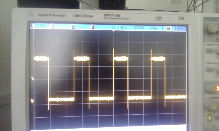
The above graph is SS pin wave. The wave width is 20 us. The frequency is 19Khz. So why am I not able to read SPI data. The graph above is for SPI calls not synced with CLKOUT from the codec in the ISR.
by guest » Wed Jul 08, 2015 16:28 UTC
the spi transfer needs to happen at the exact same time, every time. it can not be off, even by a single (codec) clock cycle, or it wont work. this is why it needs to be in the interrupt, so the timing is perfect. the SS pin needs to have a width of 1 SPI clock, and it needs to happen at the first SPI clock. it also needs to be at 44.1KHz. please have a look at the datasheet for the codec, as it has a picture of exactly what this should look like.
by youthreewire » Thu Jul 09, 2015 02:56 UTC
But if I put the SPI.transfer function in the ISR. The ISR gets stuck and the micro-controller does not respond. What should be the speed of SPI (i.e frequency)?
by guest » Thu Jul 09, 2015 05:05 UTC
SPI should be set to something relatively fast. it doesnt matter exactly what it is. between 4MHz and 8MHz should be fine. look at it on the scope, and make sure its finishing its transfer before the next interrupt should occur.
by youthreewire » Fri Jul 10, 2015 05:49 UTC
I looked at the SS pin wave on the atmega in which case the shield was working. The SS pin was high for exactly 1 us and its freuency was 44 Khz. But in case of the Due that I am experimenting with the SS pin is high for 5us with a frequency of 66.67Khz.I think the SS pin timing is faulty and should be rectified. I do not know what to do.
by guest » Fri Jul 10, 2015 06:39 UTC
the first thing to do is to get the right frequency. this is done by setting your clock divider to the right number. it should either be 127 or 128. then, you can set the pulse width by using direct port manipulation. i am assuming you are currently using digitalwrite(), and that you are writing 1, directly followed by 0. if this gives you 5us, you need to write to the pin faster, and direct manipulation using C and the port address is the fastest way of doing this. you will hae to look up online what the port variables are for the DUE. you will also have to place nop() between them to slow it down.
by youthreewire » Fri Jul 10, 2015 07:59 UTC
digitalWrite() without using nop or using nop is at 2us but the SS pin was toggling at 1us in the mega for which the library was working. Some how by changing the divider rc in the code here:
uint32_t rc = (5714285/128); //128 because we selected TIMER_CLOCK4 above
        //TC_SetRA(tc, channel, rc/2); //50% high, 50% low
        //TC_SetRC(tc, channel, rc);
        //TC_Start(tc, channel);

   TC_SetRA(TC2,TC2_CHANNEL_FOR_TCLK8,rc/2);
   TC_SetRC(TC2, TC2_CHANNEL_FOR_TCLK8,rc);
   /* start the timer */
   TC_Start(TC2, TC2_CHANNEL_FOR_TCLK8);
   /* enable the timer-specific interrupts */
   REG_TC2_IER2 = TC_IER_CPCS | TC_IER_ETRGS;
   TC2->TC_CHANNEL[TC2_CHANNEL_FOR_TCLK8].TC_IER=TC_IER_CPCS;
   TC2->TC_CHANNEL[TC2_CHANNEL_FOR_TCLK8].TC_IDR=~TC_IER_CPCS;
Is still not changing the frequency of the SS pin.It stands high for 2us and if I change the lines in the ISR I get variable delay.
by youthreewire » Fri Jul 10, 2015 09:20 UTC
I managed to turn a pin at 45.454 Khz and I am able to complete the SPI.transfers at such frequency but still my SPI data reads zero.i need to give it a time period of 22.5 microseconds but I am able to delay only by 22 us. And that is why the pin is not toggling at exactly 44100 Khz. I might have to add _asm_(nop) but how many at 96 Mhz of the Due is not know to me.
by youthreewire » Fri Jul 10, 2015 10:18 UTC
Ok, I used _asm_(nops) and now I am very close to 44Khz. This is being generated on pin12 and not the pin 10 which is assigned for SPI transfers in the code.
So what should I set this now to:
SPI.begin(10);
        SPI.setBitOrder(MSBFIRST);
        SPI.setClockDivider(10,21); // select to ss pin 10, 4 MHz// favourable values 11,21,84
        SPI.setDataMode(10,SPI_MODE0);
Does it need to be changed?
What shall I do now.
by youthreewire » Fri Jul 10, 2015 10:27 UTC
This is the ISR handler code:
void TC8_Handler()
{
  ledon1= !(ledon1);
    digitalWrite(13,ledon1);

    delayMicroseconds(1);
  digitalWriteDirect(12,LOW);
    //digitalWrite(12,LOW);


        //temp = left_out;
        //temp1 = right_out;
        temp_spi[0] = SPI.transfer(10,highByte(temp),SPI_CONTINUE);
        temp_spi[1] = SPI.transfer(10,lowByte(temp),SPI_CONTINUE);
        temp_spi[2] = SPI.transfer(10,highByte(temp),SPI_CONTINUE);
        temp_spi[3] = SPI.transfer(10,lowByte(temp),SPI_LAST);
        //left_in - (temp_spi[0]<<8)|temp_spi[1];
        //right_in = (temp_spi[2]<<8)|temp_spi[3];
        delayMicroseconds(7.5);
        __asm__("nop");
        __asm__("nop");
        __asm__("nop");
        __asm__("nop");
        __asm__("nop");
        __asm__("nop");
        __asm__("nop");
        __asm__("nop");
        __asm__("nop");
        __asm__("nop");

        __asm__("nop");
        __asm__("nop");
        __asm__("nop");
        __asm__("nop");
        __asm__("nop");
        __asm__("nop");
        __asm__("nop");
        __asm__("nop");
        __asm__("nop");
        __asm__("nop");

        __asm__("nop");
        __asm__("nop");
        __asm__("nop");
        __asm__("nop");
        __asm__("nop");
        __asm__("nop");
        __asm__("nop");
        __asm__("nop");
        __asm__("nop");
        __asm__("nop");

        __asm__("nop");
        __asm__("nop");
        __asm__("nop");
        __asm__("nop");
        __asm__("nop");
        __asm__("nop");
        __asm__("nop");
        __asm__("nop");
        __asm__("nop");
        __asm__("nop");

        __asm__("nop");
        __asm__("nop");
        __asm__("nop");
        __asm__("nop");
        __asm__("nop");
        __asm__("nop");
        __asm__("nop");
        __asm__("nop");
        __asm__("nop");
        __asm__("nop");

        __asm__("nop");
        __asm__("nop");
        __asm__("nop");
        __asm__("nop");
        __asm__("nop");
        __asm__("nop");
        __asm__("nop");
        __asm__("nop");
        __asm__("nop");
        __asm__("nop");

        __asm__("nop");
        __asm__("nop");
        __asm__("nop");


}
by youthreewire » Fri Jul 10, 2015 13:15 UTC
Now this is my final code which gives a good 44.1Khz signal for the SS pin based on timer interrupt. Also has a good SCK clock wave at 9mhz. And has the clock out signal coming from the codec configures at 5.7Mhz.
#include<SPI.h>
#include<Wire.h>
#define TC2_CHANNEL_FOR_TCLK8 2  /* presumed to correspond to XC2 */
#define LINVOL 23
#define RINVOL 23
#define LHPVOL 100
#define RHPVOL 100
#define ADCHPD 0
#define SIDEATT 0
#define SIDETONE 0
#define DACSEL 1
#define BYPASS 0
#define INSEL 0
#define MUTEMIC 1
#define MICBOOST 0
#define SAMPLE_RATE 44

volatile boolean l;
int cnt=0,startflag=0;
unsigned int temp = 0,temp1=0;
volatile int temp_spi[4];
int m1[301],m2[301];
//TC1 ch 0
int left_out,right_out;
enum Phase
   {
      TC2_INTERNAL,
      PIOD_EXTERNAL,
      TC2_EXTERNAL,
      DONE
   };

  /* enum Phase
   {
      TC2_EXTERNAL,
      TC2_EXTERNAL,
      TC2_EXTERNAL,
      DONE
   };*/

Phase phase;
int pioIRQsServiced;
int tc2IRQsServiced[3];
unsigned int status;
int upflag = 0;
bool ledon,ledon1=0;
int oldmillis=0;
volatile int left_in=30000;
volatile int right_in=30000;
volatile int myi=0;
/****************************************************************/

void PIOD_Handler(void)
{
   /* clear interrupt */
   status = REG_PIOD_ISR;
   pioIRQsServiced++;
}


/****************************************************************/
inline void digitalWriteDirect(int pin, boolean val){
  if(val) g_APinDescription[pin].pPort -> PIO_SODR = g_APinDescription[pin].ulPin;
  else    g_APinDescription[pin].pPort -> PIO_CODR = g_APinDescription[pin].ulPin;
}

inline int digitalReadDirect(int pin){
  return !!(g_APinDescription[pin].pPort -> PIO_PDSR & g_APinDescription[pin].ulPin);
}

void TC8_Handler()
{
  ledon1= !(ledon1);
    digitalWrite(13,ledon1);
  digitalWriteDirect(12,HIGH);
    delayMicroseconds(1);
  digitalWriteDirect(12,LOW);
    //digitalWrite(12,LOW);
    status = TC_GetStatus(TC2, TC2_CHANNEL_FOR_TCLK8);
   if (status & TC_SR_CPCS)
   {
      if (phase == TC2_INTERNAL)
      {
         tc2IRQsServiced[0]++;
      }
      else
      {
         tc2IRQsServiced[1]++;
      }
   }
   if (status & TC_SR_ETRGS)
   {
      tc2IRQsServiced[2]++;
   }

        //temp = left_out;
        //temp1 = right_out;
        temp_spi[0] = SPI.transfer(highByte(temp),SPI_CONTINUE);
        temp_spi[1] = SPI.transfer(lowByte(temp),SPI_CONTINUE);
        temp_spi[2] = SPI.transfer(highByte(temp),SPI_CONTINUE);
        temp_spi[3] = SPI.transfer(lowByte(temp),SPI_LAST);
        left_in - (temp_spi[0]<<8)|temp_spi[1];
        right_in = (temp_spi[2]<<8)|temp_spi[3];
        delayMicroseconds(7.5);
        __asm__("nop");
        __asm__("nop");
        __asm__("nop");
        __asm__("nop");
        __asm__("nop");
        __asm__("nop");
        __asm__("nop");
        __asm__("nop");
        __asm__("nop");
        __asm__("nop");

        __asm__("nop");
        __asm__("nop");
        __asm__("nop");
        __asm__("nop");
        __asm__("nop");
        __asm__("nop");
        __asm__("nop");
        __asm__("nop");
        __asm__("nop");
        __asm__("nop");

        __asm__("nop");
        __asm__("nop");
        __asm__("nop");
        __asm__("nop");
        __asm__("nop");
        __asm__("nop");
        __asm__("nop");
        __asm__("nop");
        __asm__("nop");
        __asm__("nop");

        __asm__("nop");
        __asm__("nop");
        __asm__("nop");
        __asm__("nop");
        __asm__("nop");
        __asm__("nop");
        __asm__("nop");
        __asm__("nop");
        __asm__("nop");
        __asm__("nop");

        __asm__("nop");
        __asm__("nop");
        __asm__("nop");
        /*__asm__("nop");
        __asm__("nop");
        __asm__("nop");
        __asm__("nop");
        __asm__("nop");
        __asm__("nop");
        __asm__("nop");

        __asm__("nop");
        __asm__("nop");
        __asm__("nop");
        __asm__("nop");
        __asm__("nop");
        __asm__("nop");
        __asm__("nop");
        __asm__("nop");
        __asm__("nop");
        __asm__("nop");

        __asm__("nop");
        __asm__("nop");
        __asm__("nop");*/


}


/****************************************************************/

void SetupPIOD(void)
{
   int result;

   /* power on PIO ("Parallel Input/Output Controller") controller D */
   pmc_enable_periph_clk(ID_PIOD);
   /* enable interrupts for PIOD */
   NVIC_EnableIRQ(PIOD_IRQn);
   /* configure PD9 as general-purpose IO pin as opposed to the TCLK8 peripheral */
   result = PIO_Configure(PIOD, PIO_INPUT, PIO_PD9, PIO_IT_RISE_EDGE);
   printf("%d <- PIO_Configure\n", result);
   /* ensure we're interrupting on the rising edge of the external clock */
   REG_PIOD_AIMER = PIO_PD9;
   REG_PIOD_ESR = PIO_PD9;
   REG_PIOD_REHLSR = PIO_PD9;
   /* enable interrupts */
   REG_PIOD_IER = PIO_PD9;
}


/****************************************************************/

void TakeDownPIOD(void)
{
   TC_Stop(TC2, TC2_CHANNEL_FOR_TCLK8);
   TC_SetRC(TC2, TC2_CHANNEL_FOR_TCLK8, 0);
   REG_PIOD_IDR = PIO_PD9;
   NVIC_DisableIRQ(TC8_IRQn);
   pmc_disable_periph_clk(ID_PIOD);
}


/****************************************************************/

void SetupTC2(bool useInternalClock)
{
   int result;

   /* "The user must configure the Power Management Controller before any access to the input line information." per 34.4.2 */
   pmc_enable_periph_clk(ID_TC8);
   /* "Using the PIO Controller requires the NVIC to be programmed first." per 34.4.3 */
   NVIC_EnableIRQ(TC8_IRQn);
   result = PIO_Configure(PIOD, PIO_PERIPH_B, PIO_ABSR_P9, PIO_DEFAULT);
   //printf("%d <- PIO_Configure\n", result);
   if (useInternalClock)
   {
      TC_Configure(TC2,
                TC2_CHANNEL_FOR_TCLK8,
                TC_CMR_TCCLKS_TIMER_CLOCK4 | TC_CMR_WAVSEL_UP_RC | TC_CMR_WAVE);
   }
   else
   {
      TC_Configure(TC2,
                TC2_CHANNEL_FOR_TCLK8,
                (TC_CMR_TCCLKS_XC2 |
                 TC_CMR_EEVTEDG_RISING |
                 TC_CMR_EEVT_XC2 |
                 TC_CMR_ENETRG |
                 TC_CMR_WAVSEL_UP_RC |
                 TC_CMR_WAVE));
   }
   //5714285
  uint32_t rc = (5714285/128); //128 because we selected TIMER_CLOCK4 above
        //TC_SetRA(tc, channel, rc/2); //50% high, 50% low
        //TC_SetRC(tc, channel, rc);
        //TC_Start(tc, channel);

   TC_SetRA(TC2,TC2_CHANNEL_FOR_TCLK8,rc/2);
   TC_SetRC(TC2, TC2_CHANNEL_FOR_TCLK8,rc);
   /* start the timer */
   TC_Start(TC2, TC2_CHANNEL_FOR_TCLK8);
   /* enable the timer-specific interrupts */
   REG_TC2_IER2 = TC_IER_CPCS | TC_IER_ETRGS;
   TC2->TC_CHANNEL[TC2_CHANNEL_FOR_TCLK8].TC_IER=TC_IER_CPCS;
   TC2->TC_CHANNEL[TC2_CHANNEL_FOR_TCLK8].TC_IDR=~TC_IER_CPCS;
  // NVIC_EnableIRQ(TC8_IRQn);
}


/****************************************************************/

void TakeDownTC2(void)
{
   TC_Stop(TC2, TC2_CHANNEL_FOR_TCLK8);
   TC_SetRC(TC2, TC2_CHANNEL_FOR_TCLK8, 0);
   REG_TC2_IDR2 = TC_IER_CPCS | TC_IER_ETRGS;
   NVIC_DisableIRQ(TC8_IRQn);
   pmc_disable_periph_clk(ID_TC8);
}

/* Clock settings (96MHz) */
 #define SYS_BOARD_OSCOUNT   (CKGR_MOR_MOSCXTST(0x8UL))
 #define SYS_BOARD_PLLAR     (CKGR_PLLAR_ONE \
                             | CKGR_PLLAR_MULA(0xfUL) \
                             | CKGR_PLLAR_PLLACOUNT(0x3fUL) \
                             | CKGR_PLLAR_DIVA(0x1UL))
 #define SYS_BOARD_MCKR      (PMC_MCKR_PRES_CLK_2 | PMC_MCKR_CSS_PLLA_CLK)

 /* Clock Definitions */
 #define SYS_UTMIPLL             (480000000UL)   /* UTMI PLL frequency */

 #define SYS_CKGR_MOR_KEY_VALUE  CKGR_MOR_KEY(0x37UL) /* Key to unlock MOR register */

 /* FIXME: should be generated by sock */
 uint32_t SystemCoreClock = CHIP_FREQ_MAINCK_RC_4MHZ;

 void SystemInit(void)
 {
     /* Set FWS according to SYS_BOARD_MCKR configuration */
     EFC0->EEFC_FMR = EEFC_FMR_FWS(4);
     EFC1->EEFC_FMR = EEFC_FMR_FWS(4);

     /* Initialize main oscillator */
     if (!(PMC->CKGR_MOR & CKGR_MOR_MOSCSEL)) {
         PMC->CKGR_MOR = SYS_CKGR_MOR_KEY_VALUE | SYS_BOARD_OSCOUNT |
                                 CKGR_MOR_MOSCRCEN | CKGR_MOR_MOSCXTEN;
         while (!(PMC->PMC_SR & PMC_SR_MOSCXTS)) {
         }
     }

     /* Switch to 3-20MHz Xtal oscillator */
     PMC->CKGR_MOR = SYS_CKGR_MOR_KEY_VALUE | SYS_BOARD_OSCOUNT |
                                CKGR_MOR_MOSCRCEN | CKGR_MOR_MOSCXTEN | CKGR_MOR_MOSCSEL;

     while (!(PMC->PMC_SR & PMC_SR_MOSCSELS)) {
     }
     PMC->PMC_MCKR = (PMC->PMC_MCKR & ~(uint32_t)PMC_MCKR_CSS_Msk) |
                               PMC_MCKR_CSS_MAIN_CLK;
     while (!(PMC->PMC_SR & PMC_SR_MCKRDY)) {
     }

     /* Initialize PLLA */
     PMC->CKGR_PLLAR = SYS_BOARD_PLLAR;
     while (!(PMC->PMC_SR & PMC_SR_LOCKA)) {
     }

     /* Switch to main clock */
     PMC->PMC_MCKR = (SYS_BOARD_MCKR & ~PMC_MCKR_CSS_Msk) | PMC_MCKR_CSS_MAIN_CLK;
     while (!(PMC->PMC_SR & PMC_SR_MCKRDY)) {
     }

     /* Switch to PLLA */
     PMC->PMC_MCKR = SYS_BOARD_MCKR;
     while (!(PMC->PMC_SR & PMC_SR_MCKRDY)) {
     }

     SystemCoreClock = CHIP_FREQ_CPU_MAX;
 }

 void SystemCoreClockUpdate(void)
 {
     /* Determine clock frequency according to clock register values */
     switch (PMC->PMC_MCKR & PMC_MCKR_CSS_Msk) {
     case PMC_MCKR_CSS_SLOW_CLK: /* Slow clock */
         if (SUPC->SUPC_SR & SUPC_SR_OSCSEL) {
             SystemCoreClock = CHIP_FREQ_XTAL_32K;
         } else {
             SystemCoreClock = CHIP_FREQ_SLCK_RC;
         }
         break;
     case PMC_MCKR_CSS_MAIN_CLK: /* Main clock */
         if (PMC->CKGR_MOR & CKGR_MOR_MOSCSEL) {
             SystemCoreClock = CHIP_FREQ_XTAL_12M;
         } else {
             SystemCoreClock = CHIP_FREQ_MAINCK_RC_4MHZ;

             switch (PMC->CKGR_MOR & CKGR_MOR_MOSCRCF_Msk) {
             case CKGR_MOR_MOSCRCF_4_MHz:
                 break;
             case CKGR_MOR_MOSCRCF_8_MHz:
                 SystemCoreClock *= 2U;
                 break;
             case CKGR_MOR_MOSCRCF_12_MHz:
                 SystemCoreClock *= 3U;
                 break;
             default:
                 break;
             }
         }
         break;
     case PMC_MCKR_CSS_PLLA_CLK: /* PLLA clock */
     case PMC_MCKR_CSS_UPLL_CLK: /* UPLL clock */
         if (PMC->CKGR_MOR & CKGR_MOR_MOSCSEL) {
             SystemCoreClock = CHIP_FREQ_XTAL_12M;
         } else {
             SystemCoreClock = CHIP_FREQ_MAINCK_RC_4MHZ;

             switch (PMC->CKGR_MOR & CKGR_MOR_MOSCRCF_Msk) {
             case CKGR_MOR_MOSCRCF_4_MHz:
                 break;
             case CKGR_MOR_MOSCRCF_8_MHz:
                 SystemCoreClock *= 2U;
                 break;
             case CKGR_MOR_MOSCRCF_12_MHz:
                 SystemCoreClock *= 3U;
                 break;
             default:
                 break;
             }
         }
         if ((PMC->PMC_MCKR & PMC_MCKR_CSS_Msk) == PMC_MCKR_CSS_PLLA_CLK) {
             SystemCoreClock *= ((((PMC->CKGR_PLLAR) & CKGR_PLLAR_MULA_Msk) >>
                                           CKGR_PLLAR_MULA_Pos) + 1U);
             SystemCoreClock /= ((((PMC->CKGR_PLLAR) & CKGR_PLLAR_DIVA_Msk) >>
                                            CKGR_PLLAR_DIVA_Pos));
         } else {
             SystemCoreClock = SYS_UTMIPLL / 2U;
         }
         break;
     }

     if ((PMC->PMC_MCKR & PMC_MCKR_PRES_Msk) == PMC_MCKR_PRES_CLK_3) {
         SystemCoreClock /= 3U;
     } else {
         SystemCoreClock >>= ((PMC->PMC_MCKR & PMC_MCKR_PRES_Msk) >>
                                        PMC_MCKR_PRES_Pos);
     }
 }

 void TC3_Handler()
{
        TC_GetStatus(TC1, 0);

        /*temp = random(65535);
        //temp = left_out;
        //temp1 = right_out;
        temp_spi[0] = SPI.transfer(10,highByte(temp),SPI_CONTINUE);
        temp_spi[1] = SPI.transfer(10,lowByte(temp),SPI_CONTINUE);
        temp_spi[2] = SPI.transfer(10,highByte(temp),SPI_CONTINUE);
        temp_spi[3] = SPI.transfer(10,lowByte(temp),SPI_LAST);
        //left_in - (temp_spi[0]<<8)|temp_spi[1];
        //right_in = (temp_spi[2]<<8)|temp_spi[3];
        /*Serial.println("Hello");
        Serial.println(temp_spi[0]);
        Serial.println(temp_spi[1]);
        Serial.println(temp_spi[2]);
        Serial.println(temp_spi[3]);*/
}

void startTimer(Tc *tc, uint32_t channel, IRQn_Type irq, uint32_t frequency) {
        pmc_set_writeprotect(false);
        pmc_enable_periph_clk((uint32_t)irq);
        TC_Configure(tc, channel, TC_CMR_WAVE | TC_CMR_WAVSEL_UP_RC | TC_CMR_TCCLKS_TIMER_CLOCK4);
        uint32_t rc = VARIANT_MCK/128/frequency; //128 because we selected TIMER_CLOCK4 above
        TC_SetRA(tc, channel, rc/2); //50% high, 50% low
        TC_SetRC(tc, channel, rc);
        TC_Start(tc, channel);
        tc->TC_CHANNEL[channel].TC_IER=TC_IER_CPCS;
        tc->TC_CHANNEL[channel].TC_IDR=~TC_IER_CPCS;
        NVIC_EnableIRQ(irq);
}

 void AudioCodec_init() {
        randomSeed(analogRead(0));
        SPI.begin();
        SPI.setBitOrder(MSBFIRST);
        SPI.setClockDivider(21); // select to ss pin 10, 4 MHz// favourable values 11,21,84
        SPI.setDataMode(SPI_MODE0);

        // setup i2c pins and configure codec
        // the new Wire library has trouble with 0x00, so (uint8_t) is added
        // To change the Wire interface speed, go to:
        // <path_from_arduino>\hardware\arduino\sam\libraries\Wire\Wire.h
        // and change the parameters TWI_CLOCK, RECV_TIMEOUT and XMIT_TIMEOUT
        // to the desire frequency.
        int temp_wire1;
        int temp_wire2;

        Wire.begin();
        Wire.beginTransmission(0x1a);
        Wire.write(0x0c); // power reduction register
        Wire.write((uint8_t)0x00); // turn everything on
        temp_wire1 = Wire.endTransmission();

        Wire.beginTransmission(0x1a);
        Wire.write(0x0e); // digital data format
        Wire.write(0x03); // 16b SPI mode
        temp_wire2 = Wire.endTransmission();

        Serial.println(temp_wire1);
        Serial.println(temp_wire2);

        Wire.beginTransmission(0x1a);
        Wire.write((uint8_t)0x00); // left in setup register
        Wire.write((uint8_t)LINVOL);
        Wire.endTransmission();

        Wire.beginTransmission(0x1a);
        Wire.write(0x02); // right in setup register
        Wire.write((uint8_t)RINVOL);
        Wire.endTransmission();

        Wire.beginTransmission(0x1a);
        Wire.write(0x04); // left headphone out register
        Wire.write((uint8_t)LHPVOL);
        Wire.endTransmission();

        Wire.beginTransmission(0x1a);
        Wire.write(0x06); // right headphone out register
        Wire.write((uint8_t)RHPVOL);
        Wire.endTransmission();

        Wire.beginTransmission(0x1a);
        Wire.write(0x0a); // digital audio path configuration
        Wire.write((uint8_t)ADCHPD);
        Wire.endTransmission();

        Wire.beginTransmission(0x1a);
        Wire.write(0x08); // analog audio pathway configuration
        Wire.write((uint8_t)((SIDEATT << 6)|(SIDETONE << 5)|(DACSEL << 4)|(BYPASS << 3)|(INSEL << 2)|(MUTEMIC << 1)|(MICBOOST << 0)));
        Wire.endTransmission();

        Wire.beginTransmission(0x1a);
        Wire.write(0x10); // clock configuration
        #if SAMPLE_RATE == 88
          Wire.write(0xbc);
        #elif SAMPLE_RATE == 44
          Wire.write(0xa0);
        #elif SAMPLE_RATE == 22
          Wire.write(0xe0);
        #elif SAMPLE_RATE == 8
          Wire.write(0xac);
        #elif SAMPLE_RATE == 2
          Wire.write(0xce);
        #endif
        Wire.endTransmission();

        Wire.beginTransmission(0x1a);
        Wire.write(0x12); // codec enable
        Wire.write(0x01);
        Wire.endTransmission();

}
/****************************************************************/

void setup(void)
{
   pinMode(12,OUTPUT);
   pinMode(13,OUTPUT);
   //SPI.begin();
   SystemInit();
   SystemCoreClockUpdate();
   AudioCodec_init();
   //startTimer(TC1, 0, TC3_IRQn, 44100);
   Serial3.begin(6000000);
   Serial3.println("Ranjan test");
   Serial3.println("start with TC2 internal\n");
   //SetupTC2(false);
}


/****************************************************************/

void loop(void)
{

   //Serial2.println("Rnnjan in loop");
    // temp_spi[0] = SPI.transfer(10,highByte(temp),SPI_CONTINUE);
  phase=TC2_EXTERNAL;
  /*if(startflag==0)
  //if(1)
  {
  //SetupPIOD();
  SetupTC2(false);
  startflag=1;
  }*/

  //Serial.println(phase);
   switch (phase)
   {
      case TC2_INTERNAL:
         if (tc2IRQsServiced[0] > 250000)
         {
            phase = PIOD_EXTERNAL;
            TakeDownTC2();
            printf("PASSED\nswitch to PIOD\n");
            SetupPIOD();
         }
         break;
      case PIOD_EXTERNAL:
         if (pioIRQsServiced > 20)
         {
            phase = TC2_EXTERNAL;
            TakeDownTC2();
            printf("PASSED\nswitch to TC2 external\n");
            SetupTC2(false);
         }
         break;
      case TC2_EXTERNAL:
      SetupTC2(false);
         if (tc2IRQsServiced[1] > 20)
         {
            printf("PASSED!!!\n");
            for ( ; ; );
         }
         break;
      default:
         break;
   }
   //delay(1000);
   Serial3.println(temp_spi[1]);
   //Serial3.println(right_in);
  // printf("PIO IRQs: %d, CPCS internal IRQs: %d, CPCS external IRQs: %d, ETRGS external IRQs: %d, status: %08x, CV2: %d\n", pioIRQsServiced, tc2IRQsServiced[0], tc2IRQsServiced[1], tc2IRQsServiced[2], status, REG_TC2_CV2);

}
If you can try this code and let me know what is still wrong I will be thankful. It some times gets some values from the mic in temp-spi[0] variables but that is like very sparse. A 100 values might have 2 or 3 useful values. Some times we get a bunch of values.For some reason this code stops spitting the serial port values after some time. Also this uses an FT232H configured at 6000000 bps (6mbps) on Serial port 3.
by guest » Fri Jul 10, 2015 17:59 UTC
what happens if you get rid of the delayMicroseconds() here? does the pulse width decrease? also, how does the pulse align with the SPI clock? does it match the datasheet?
digitalWriteDirect(12,HIGH);
delayMicroseconds(1);
digitalWriteDirect(12,LOW);
and what happens when you get rid of this stuff? it shouldnt matter either way, as timing should be determined by the counter, not the interrupt length.
delayMicroseconds(7.5);
        __asm__("nop");
        __asm__("nop");
        __asm__("nop");
by youthreewire » Sat Jul 11, 2015 05:06 UTC
guest wrote:what happens if you get rid of the delayMicroseconds() here? does the pulse width decrease? also, how does the pulse align with the SPI clock? does it match the datasheet?
digitalWriteDirect(12,HIGH);
delayMicroseconds(1);
digitalWriteDirect(12,LOW);
Yes the pulse width gets reduced if I get rid of it. Actually I checked again on the mega and found that the pin SS is high for 200ns and I made changes to my code accordingly.
and what happens when you get rid of this stuff? it shouldnt matter either way, as timing should be determined by the counter, not the interrupt length.
delayMicroseconds(7.5);
        __asm__("nop");
        __asm__("nop");
        __asm__("nop");
Yes the phase of signal low get effected if I change the delayMicoseconds and nops here.
also, how does the pulse align with the SPI clock? does it match the datasheet?
I dont understand this.
Here is the code for my updated ISR handler.
void TC8_Handler()
{
  ledon1= !(ledon1);
    digitalWrite(13,ledon1);
  digitalWriteDirect(12,HIGH);
    //delayMicroseconds(1);
   __asm__("nop");
   __asm__("nop");
   __asm__("nop");
   __asm__("nop");
   __asm__("nop");
   __asm__("nop");
   __asm__("nop");
   __asm__("nop");
   __asm__("nop");
   __asm__("nop");
   __asm__("nop");

  digitalWriteDirect(12,LOW);
    //digitalWrite(10,LOW);
    status = TC_GetStatus(TC2, TC2_CHANNEL_FOR_TCLK8);
   if (status & TC_SR_CPCS)
   {
      if (phase == TC2_INTERNAL)
      {
         tc2IRQsServiced[0]++;
      }
      else
      {
         tc2IRQsServiced[1]++;
      }
   }
   if (status & TC_SR_ETRGS)
   {
      tc2IRQsServiced[2]++;
   }

        //temp = left_out;
        //temp1 = right_out;
        temp_spi[0] = SPI.transfer(10,highByte(temp),SPI_CONTINUE);
        temp_spi[1] = SPI.transfer(10,lowByte(temp),SPI_CONTINUE);
        temp_spi[2] = SPI.transfer(10,highByte(temp),SPI_CONTINUE);
        temp_spi[3] = SPI.transfer(10,lowByte(temp),SPI_LAST);
        left_in - (temp_spi[0]<<8)|temp_spi[1];
        right_in = (temp_spi[2]<<8)|temp_spi[3];
        delayMicroseconds(9);
        __asm__("nop");
        __asm__("nop");
        __asm__("nop");
        __asm__("nop");
        __asm__("nop");
        __asm__("nop");
}
by youthreewire » Sat Jul 11, 2015 06:08 UTC
The due is acting crazy. Some times the delayMicroseconds has an effect and some times it doesnt.
by guest » Sat Jul 11, 2015 17:28 UTC
SPI will not work unless you toggle the SS pin correctly. please read the datasheet for the WM8731:
http://wiki.openmusiclabs.com/wiki/Audi ... WM8731.pdf
page 35 - DSP mode, mode B.
you will need to connect the SPI clock pin, and the new SS pin (the one you are toggling manually) to your oscilloscope, and take a look at when they go high/low with respect to the first clock cycle of the SPI clock. when it goes high is not as critical as when it goes low. it needs to align with the first clock pulse.
also, im not sure what this code is doing, but it should be put after the SPI transfers:
    status = TC_GetStatus(TC2, TC2_CHANNEL_FOR_TCLK8);
   if (status & TC_SR_CPCS)
   {
      if (phase == TC2_INTERNAL)
      {
         tc2IRQsServiced[0]++;
      }
      else
      {
         tc2IRQsServiced[1]++;
      }
   }
   if (status & TC_SR_ETRGS)
   {
      tc2IRQsServiced[2]++;
   }
by youthreewire » Sun Jul 12, 2015 02:49 UTC
That piece of code just counts the ISR serviced. I removed it in my latest fix. But as you said a delay in the ISR should not effect the frequency at which ISR appears.It is strange.
by youthreewire » Thu Jul 30, 2015 06:24 UTC
Today I tried the Arudino Hifi I2S driver which uses the Due's SSC controller to communicate with the WM8731 codec over I2S mode. Note now I am using the Mikro audio codec shield and it has ADCLRC and DACLRC as separate pins.Now my I2C interface is just as the earlier one in the code that I posted but now I am using Hi-FI with it.I am just trying to echo data from the microphone to the headphones but I dont get any output.I am not sure if I am configuring the shield correctly over I2C. Could you help me figure out what the problem is?
Here is my newer code:
/*
  This example uses the HiFi library to connect with a Cirrus CS4271 audio
  codec.  The codec has been configured to generate all the clocks and the
  Arduino will sync to them.  The codec is using I2S mode to communicate
  with the SSC peripheral.

  The sketch takes any data is receives from the codec and sends it right
  back out.

  This sketch is free software; you can redistribute it and/or
  modify it under the terms of the GNU Lesser General Public
  License as published by the Free Software Foundation; either
  version 2.1 of the License, or (at your option) any later version.

  This library is distributed in the hope that it will be useful,
  but WITHOUT ANY WARRANTY; without even the implied warranty of
  MERCHANTABILITY or FITNESS FOR A PARTICULAR PURPOSE.
  See the GNU Lesser General Public License for more details.

  You should have received a copy of the GNU Lesser General Public
  License along with this library; if not, write to the Free Software
  Foundation, Inc., 51 Franklin St, Fifth Floor, Boston, MA  02110-1301  USA
*/

#include <HiFi.h>
#include <Wire.h>
#define LINVOL 23
#define RINVOL 23
#define LHPVOL 100
#define RHPVOL 100
#define ADCHPD 0
#define SIDEATT 0
#define SIDETONE 0
#define DACSEL 1
#define BYPASS 0
#define INSEL 0
#define MUTEMIC 1
#define MICBOOST 0
#define SAMPLE_RATE 44

void codecTxReadyInterrupt(HiFiChannelID_t);
void codecRxReadyInterrupt(HiFiChannelID_t);

static uint32_t ldat = 0;
static uint32_t rdat = 0;


void AudioCodec_init() {
        /*randomSeed(analogRead(0));
        SPI.begin(10);
        SPI.setBitOrder(MSBFIRST);
        SPI.setClockDivider(10,84); // select to ss pin 10, 4 MHz// favourable values 11,21,84
        SPI.setDataMode(10,SPI_MODE0);*/

        // setup i2c pins and configure codec
        // the new Wire library has trouble with 0x00, so (uint8_t) is added
        // To change the Wire interface speed, go to:
        // <path_from_arduino>\hardware\arduino\sam\libraries\Wire\Wire.h
        // and change the parameters TWI_CLOCK, RECV_TIMEOUT and XMIT_TIMEOUT
        // to the desire frequency.
        int temp_wire1;
        int temp_wire2;

        Wire.begin();
        Wire.beginTransmission(0x1a);
        Wire.write(0x0c); // power reduction register
        Wire.write((uint8_t)0x00); // turn everything on
        temp_wire1 = Wire.endTransmission();

        Wire.beginTransmission(0x1a);
        Wire.write(0x0e); // digital data format
        Wire.write(0x03); // 16b SPI mode
        temp_wire2 = Wire.endTransmission();

        //Serial.println(temp_wire1);
        //Serial.println(temp_wire2);

        Wire.beginTransmission(0x1a);
        Wire.write((uint8_t)0x00); // left in setup register
        Wire.write((uint8_t)LINVOL);
        Wire.endTransmission();

        Wire.beginTransmission(0x1a);
        Wire.write(0x02); // right in setup register
        Wire.write((uint8_t)RINVOL);
        Wire.endTransmission();

        Wire.beginTransmission(0x1a);
        Wire.write(0x04); // left headphone out register
        Wire.write((uint8_t)LHPVOL);
        Wire.endTransmission();

        Wire.beginTransmission(0x1a);
        Wire.write(0x06); // right headphone out register
        Wire.write((uint8_t)RHPVOL);
        Wire.endTransmission();

        Wire.beginTransmission(0x1a);
        Wire.write(0x0a); // digital audio path configuration
        Wire.write((uint8_t)ADCHPD);
        Wire.endTransmission();

        Wire.beginTransmission(0x1a);
        Wire.write(0x08); // analog audio pathway configuration
        Wire.write((uint8_t)((SIDEATT << 6)|(SIDETONE << 5)|(DACSEL << 4)|(BYPASS << 3)|(INSEL << 2)|(MUTEMIC << 1)|(MICBOOST << 0)));
        Wire.endTransmission();

        Wire.beginTransmission(0x1a);
        Wire.write(0x10); // clock configuration
        #if SAMPLE_RATE == 88
          Wire.write(0xbc);
        #elif SAMPLE_RATE == 44
          Wire.write(0xa0);
        #elif SAMPLE_RATE == 22
          Wire.write(0xe0);
        #elif SAMPLE_RATE == 8
          Wire.write(0xac);
        #elif SAMPLE_RATE == 2
          Wire.write(0xce);
        #endif
        Wire.endTransmission();

        Wire.beginTransmission(0x1a);
        Wire.write(0x12); // codec enable
        Wire.write(0x01);
        Wire.endTransmission();

}


void setup() {

  // set codec into reset
  pinMode(7, OUTPUT);
  digitalWrite(7, LOW);
  Serial.begin(38400);
  AudioCodec_init();
  HiFi.begin();

  // Configure transmitter for 2 channels, external TK/TF clocks, 32 bit per
  // channel (data less than 32-bit is left justified in the 32 bit word, but
  // codec config needs 32 clocks per channel).
  HiFi.configureTx(HIFI_AUDIO_MODE_STEREO, HIFI_CLK_MODE_USE_EXT_CLKS, 32);

  // Same config as above, except sync the receiver to transmitter (RK/RF
  // clock signals not needed)
  HiFi.configureRx(HIFI_AUDIO_MODE_STEREO, HIFI_CLK_MODE_USE_TK_RK_CLK, 32);

  // Since we've decided to sync the receiver to the transmitter, we could
  // handle both reading and writing in a single interrupt (receive or
  // transmit).  This example uses both just for demonstration purposes.
  HiFi.onTxReady(codecTxReadyInterrupt);
  HiFi.onRxReady(codecRxReadyInterrupt);

  // release codec from reset
  digitalWrite(7, HIGH);

  // Enable both receiver and transmitter.
  HiFi.enableRx(true);
  HiFi.enableTx(true);
}

void loop() {

Serial.print(ldat);
Serial.print(" ");
Serial.println(rdat);

}


void codecTxReadyInterrupt(HiFiChannelID_t channel)
{
  if (channel == HIFI_CHANNEL_ID_1)
  {
    // Left channel
    HiFi.write(ldat);
  }
  else
  {
    // Right channel
    HiFi.write(rdat);
  }
}

void codecRxReadyInterrupt(HiFiChannelID_t channel)
{
  if (channel == HIFI_CHANNEL_ID_1)
  {
    // Left channel
    ldat = HiFi.read();
  }
  else
  {
    // Right channel
    rdat = HiFi.read();
  }
}
by youthreewire » Thu Jul 30, 2015 06:25 UTC
I remember you telling me that the codec in your shield is working in DSP mode B. How do I set it to I2S mode ?
by youthreewire » Thu Jul 30, 2015 11:10 UTC
I read the data sheet of WM8731 and as per page 39 I changed the code here for the register "audio data interface format" but still I am not getting any data from the codec.
Wire.beginTransmission(0x1a);
        Wire.write(0x0e); // digital data format
        //Wire.write(0x03); // 16b SPI mode
        Wire.write(0x02);
My connections to the codec shield and the Due are as in this table.
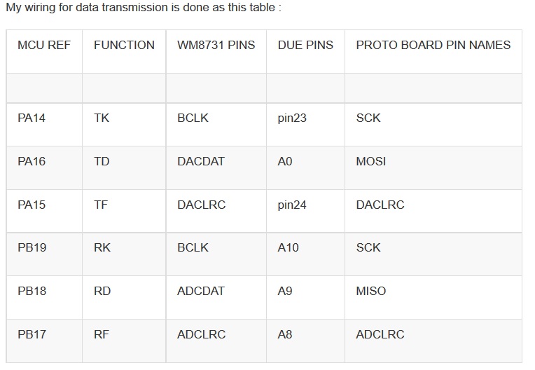
by guest » Thu Jul 30, 2015 17:54 UTC
on the codecshield, there is only 1 BCK and 1 LRCK, but the DUE has 2 of each. how are you connecting these up? also, be sure to setup the DUE as I2S master. then take a look at the signals on the scope to see if they look right (match the format shown in the datasheet).
by youthreewire » Fri Jul 31, 2015 06:34 UTC
Back to the old code(not using the Hi-Fi ibrary) ,I am attaching the scope plots. The yellow one is the SS (slave select) pin wave and the green one is the SPI clock.Their units are also different.One is in micro seconds where as the other is in nano seconds.I dont know if the graphs are right and mean what you mentioned that the SS pin cycle needs to match with the first clock cycle of the SPI.
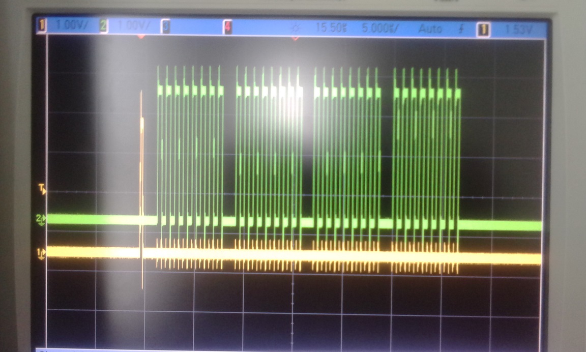
zoomed in
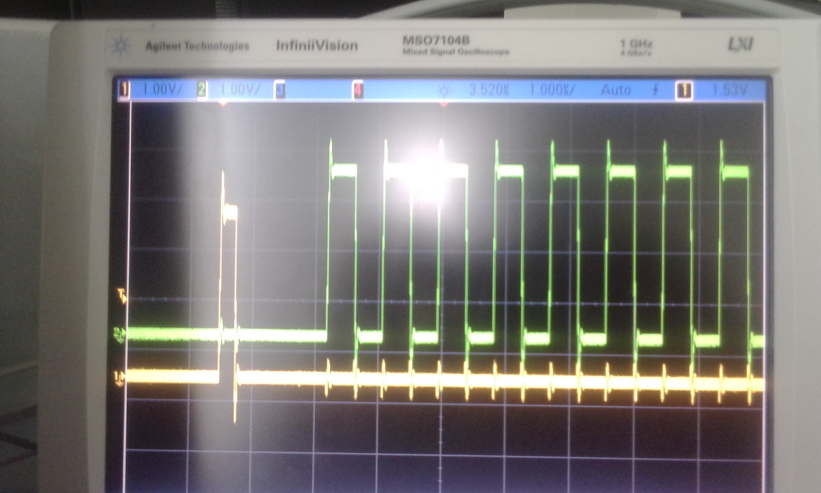
zoomed out.
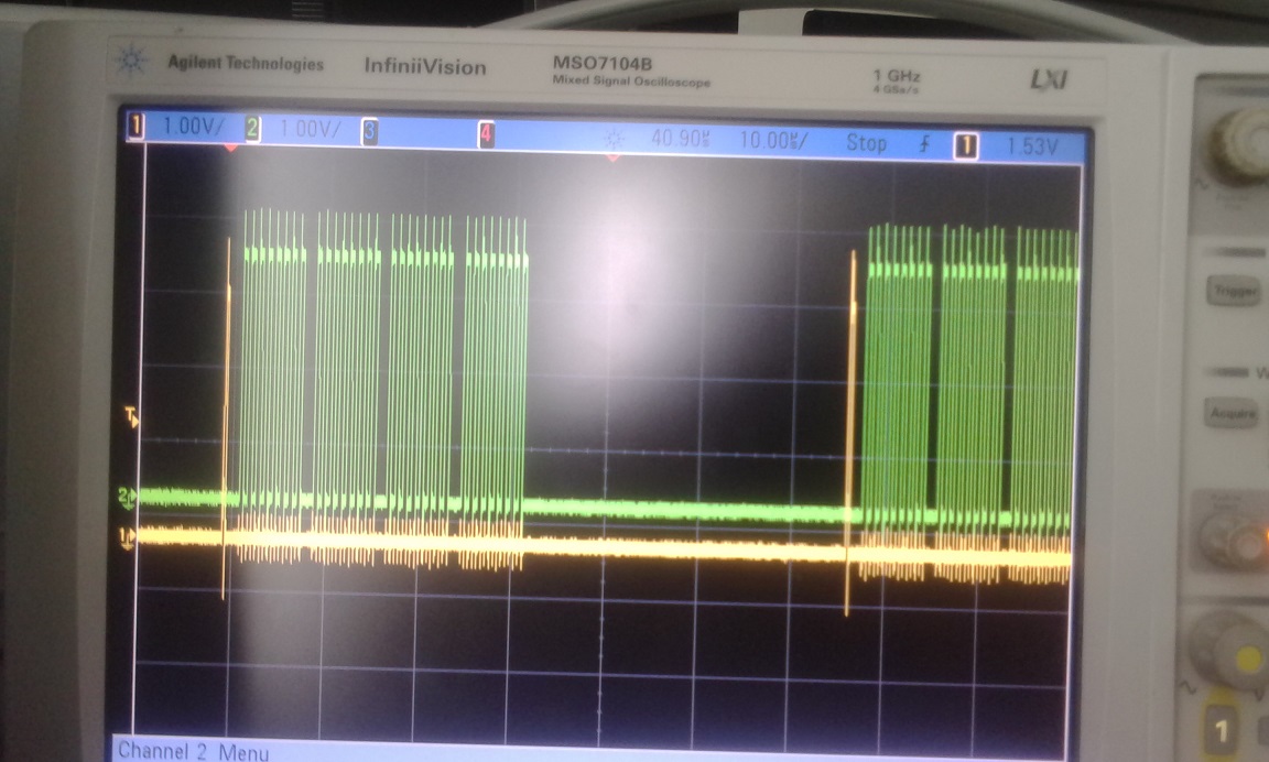
The SS pin high (yellow) appears to come before the SPI transfers(green) but I do not know what the alignment should look like
by youthreewire » Fri Jul 31, 2015 09:04 UTC
Should it look like this?I dont know what correspond to what? Is the LRC the SS pin wave? And BCLK the SPI Clock?
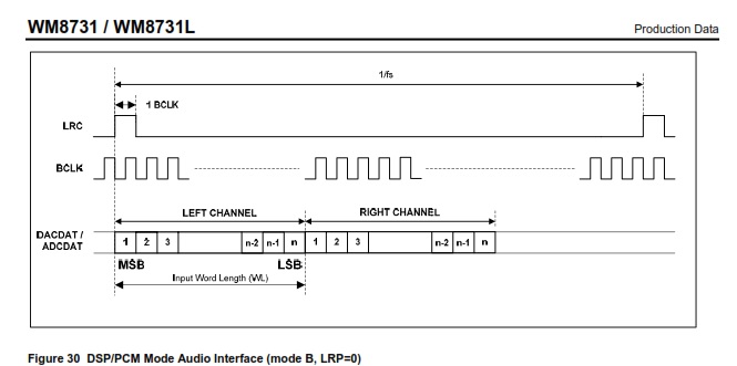
by youthreewire » Fri Jul 31, 2015 09:12 UTC
I look at your library and it appears you are toggiling the SS pin and waiting for one transfer and then you are toggling the pin again and then the rest of the transfer takes place.
Your code from the library.
 int _out_temp = _lout;
  PORTB |= (1<<PORTB2);  // toggle ss pina
  asm volatile ("out %0, %B1" : : "I" (_SFR_IO_ADDR(SPDR)), "r" (_out_temp) );
  PORTB &= ~(1<<PORTB2); // toggle ss pin
  while(!(SPSR & (1<<SPIF))){ // wait for data transfer to complete
  }
To get such an effect I might have to dig into the C code to do the SPI transfers and toggle the pin at the falling edge of the SCK.Am I right in all this?
By the way what are you doing here in this line:
asm volatile ("out %0, %B1" : : "I" (_SFR_IO_ADDR(SPDR)), "r" (_out_temp) );
by youthreewire » Fri Jul 31, 2015 10:24 UTC
I looked at this code from the Maple library.It appears you have set the SS pin high all during the first byte transfer.Should the SS pin be high at the first byte transfer and then made low or should it be high for the first bit transfer (out of the first 8 bits in the first byte leftour or right out etc).
static inline void AudioCodec_data(int16* _lin, int16* _rin, int16 _lout, int16 _rout) {

  GPIOA_BASE->BSRR = 0x00000010; // set ss high
  SPI1_BASE->DR = _lout; // send out left data
  asm volatile ("nop"); // delay for appropriate timing
  asm volatile ("nop");
  asm volatile ("nop");
  asm volatile ("nop");
  asm volatile ("nop");
  asm volatile ("nop");
  asm volatile ("nop");
  asm volatile ("nop");
  asm volatile ("nop");
  GPIOA_BASE->BSRR = 0x00100000; // set ss low
  while (!(SPI1_BASE->SR & (1 << SPI_SR_TXE_BIT))) { // wait for data to be sent
  }
  SPI1_BASE->DR = _rout; // send out right data
  while (!(SPI1_BASE->SR & (1 << SPI_SR_RXNE_BIT))) { // wait for data to arrive
  }
  *_lin = SPI1_BASE->DR; // recieve left data
  while (!(SPI1_BASE->SR & (1 << SPI_SR_RXNE_BIT))) { // wait for data to arrive
  }
  *_rin = SPI1_BASE->DR; // recieve right data
}
by guest » Fri Jul 31, 2015 18:09 UTC
you are getting closer. the scope shots show the problem - the SS pin is toggled too early. you are correct that the SS should be the LRC and the SCK the BCK in the WM8731 datasheet pictures. try to replicate what i did for the maple, and then check the scope again and see what happens. basically, do the following:
set SS high
transfer first data packet on SPI
set SS low
by youthreewire » Sat Aug 01, 2015 04:42 UTC
First data packet means a byte or a bit. Because I am thinking that it is first bit, I already tried to make it low after the first byte but I did not get any data.
by youthreewire » Sat Aug 01, 2015 05:25 UTC
Here is the code for SPI transfer
void SPIWrite(uint8_t val)
{
    //Wait for previous transfer to complete
    while ((SPI0->SPI_SR & SPI_SR_TXEMPTY) == 0);

    //load the Transmit Data Register with the value to transmit
    SPI0->SPI_TDR = val;

    //Wait for data to be transferred to serializer
    while ((SPI0->SPI_SR & SPI_SR_TDRE) == 0);
}
How shall I sync it up? I will look at your library and decide that.I will post the updated ISR handler code later.
The following is Maple code.I am not able to understand this.
static inline void AudioCodec_data(int16* _lin, int16* _rin, int16 _lout, int16 _rout) {

  GPIOA_BASE->BSRR = 0x00000010; // set ss high
  SPI1_BASE->DR = _lout; // send out left data
  asm volatile ("nop"); // delay for appropriate timing
  asm volatile ("nop");
  asm volatile ("nop");
  asm volatile ("nop");
  asm volatile ("nop");
  asm volatile ("nop");
  asm volatile ("nop");
  asm volatile ("nop");
  asm volatile ("nop");
  GPIOA_BASE->BSRR = 0x00100000; // set ss low
  while (!(SPI1_BASE->SR & (1 << SPI_SR_TXE_BIT))) { // wait for data to be sent
  }
  SPI1_BASE->DR = _rout; // send out right data
  while (!(SPI1_BASE->SR & (1 << SPI_SR_RXNE_BIT))) { // wait for data to arrive
  }
  *_lin = SPI1_BASE->DR; // recieve left data
  while (!(SPI1_BASE->SR & (1 << SPI_SR_RXNE_BIT))) { // wait for data to arrive
  }
  *_rin = SPI1_BASE->DR; // recieve right data
}
by youthreewire » Sat Aug 01, 2015 08:29 UTC
I wrote the following code for the SPI transfers in the ISR. Is this right?
void TC8_Handler()
{
  ledon1 = !(ledon1);
  digitalWrite(13, ledon1);
  //delayMicroseconds(3);

  while ((SPI0->SPI_SR & SPI_SR_TXEMPTY) == 0);
  digitalWriteDirect(12, HIGH);
  SPI0->SPI_TDR = lout;
  __asm__("nop");
  __asm__("nop");
  __asm__("nop");
  __asm__("nop");
  __asm__("nop");
  __asm__("nop");
  __asm__("nop");
  __asm__("nop");
  __asm__("nop");
  __asm__("nop");
  __asm__("nop");


 while((SPI0->SPI_SR & SPI_SR_TDRE)==0)
 {;}
  digitalWriteDirect(12, LOW);
 SPI0->SPI_TDR = rout;
 while((SPI0->SPI_SR & SPI_SR_TDRE)==0)
 {;}
 while((SPI0->SPI_SR & SPI_SR_RDRF) == 0)
 {;}
 lin = SPI0->SPI_RDR;
  while((SPI0->SPI_SR & SPI_SR_RDRF) == 0)
 {;}
 rin = SPI0->SPI_RDR;

  //temp = left_out;
  //temp1 = right_out;
 // temp_spi[0] = SPI.transfer(10, highByte(temp), SPI_CONTINUE);

  //temp_spi[1] = SPI.transfer(10, lowByte(temp), SPI_CONTINUE);
  //temp_spi[2] = SPI.transfer(10, highByte(temp), SPI_CONTINUE);
  //temp_spi[3] = SPI.transfer(10, lowByte(temp), SPI_LAST);
  //left_in - (temp_spi[0]<<8)|temp_spi[1];
  //right_in = (temp_spi[2]<<8)|temp_spi[3];
  delayMicroseconds(22);
  __asm__("nop");
  __asm__("nop");
  __asm__("nop");
  __asm__("nop");
  __asm__("nop");
  __asm__("nop");
  status = TC_GetStatus(TC2, TC2_CHANNEL_FOR_TCLK8);
}
by youthreewire » Sat Aug 01, 2015 09:52 UTC
I am getting this graph.As you can see the yellow peak now overlaps with the green peak.Not at the cycle of the rising edge but just at the falling edge. Is this graph right or should I change something more?
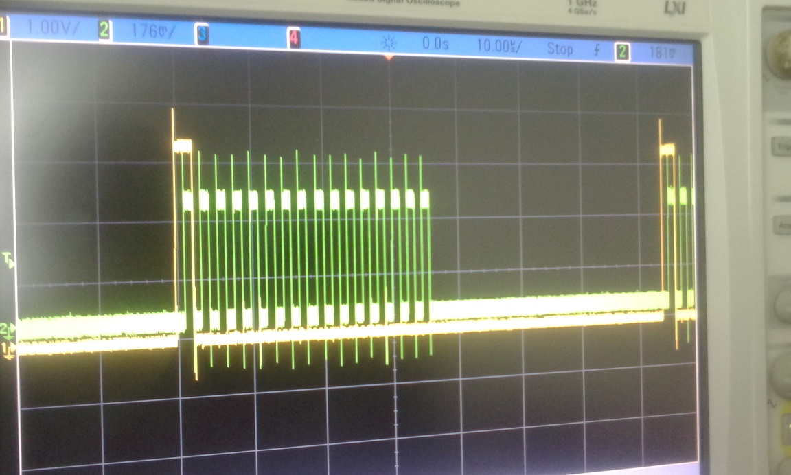
"lout" reads as 0 and "lin" reads a constant 917504 .What shall I do now?
by youthreewire » Sat Aug 01, 2015 11:05 UTC
I tried now again and I get these values (it is either of these 3 or 4 values).
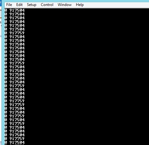
by youthreewire » Sat Aug 01, 2015 11:11 UTC
I am getting some thing on the "lin" and "rin" but it is always a number starting with 91000 and I think it might be because these integer variables in Due are 32 bit but the values read from the codec are 16 bit. Could you please give your opinion on this.
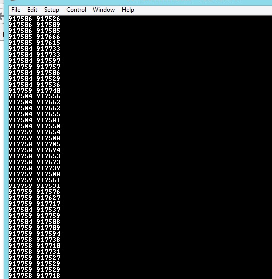
by youthreewire » Sat Aug 01, 2015 11:19 UTC
When I am making noise before the mic these values are changing but I now have to see if they can be set to 16 bit. I did lout=lin and rout=rin but I do not get an echo back. Now I have declared these integers as short int which means 16 bit but the ISR gets stuck if I used short int. I do not know how to get an echo now. Could you test my code if you have a Due?
by youthreewire » Sat Aug 01, 2015 11:58 UTC
WIERD thing, When I connect the oscilloscope probes to tap the SCK and SS pin I get the mic values responding to sound and additionally if I change the sensitivity (by pressing a button) on the probe I also get an echo back on one of the speakers of the headphone.Now when I remove the probes I just constant values 917504. What could be the problem?
by guest » Sun Aug 02, 2015 06:22 UTC
that oscilloscope shot looks good.
so, if i understand correctly, it works when the scope is connected, but not elsewise? if so, first - congratulations on getting it working, but second, it must be ringing on the lines messing things up. put a 10pF capacitor where you had the scope probe and see if it makes it work.
by youthreewire » Sun Aug 02, 2015 13:30 UTC
It worked for quite some time when I connected the probe but now it is not working either if I connect to scope or not. So how shall I debug this?I am getting constant values like 917504 and these values stop coming from the serial port after some time. The serial port gets stuck but the ISR keeps running (as I am blinking an led on pin13). Please let me know.
But there is some other problem. Right now I am getting only 16 bits.I might have to add some more lines in the SPI to get two 16 bits (i.e 32 bits in total for two 16 bit values like lin and rin). My main loop stops spitting out serial port values but he ISR still runs.
by guest » Sun Aug 02, 2015 16:20 UTC
can you post your SPI code?
i wouldnt use the serial port at all at this point. it just makes it more dfficult. just do a loopback test to see if it works (rout = rin, etc). also, it stops working if the clock gets out of sync. so make sure that the timer/counter block is working properly. its possible its off by just a bit, goes in and out of sync.
by youthreewire » Mon Aug 03, 2015 03:04 UTC
I already posted my SPI code. Anyways it is here again
void TC8_Handler()
{
  ledon1 = !(ledon1);
  digitalWrite(13, ledon1);

  while ((SPI0->SPI_SR & SPI_SR_TXEMPTY) == 0);
  digitalWriteDirect(12, HIGH);
  SPI0->SPI_TDR = lout;
  __asm__("nop");
  __asm__("nop");
  __asm__("nop");
  __asm__("nop");
  __asm__("nop");
  __asm__("nop");
  __asm__("nop");
  __asm__("nop");
  __asm__("nop");
  __asm__("nop");
  __asm__("nop");


 while((SPI0->SPI_SR & SPI_SR_TDRE)==0)
 {;}
  digitalWriteDirect(12, LOW);
 SPI0->SPI_TDR = rout;
 while((SPI0->SPI_SR & SPI_SR_TDRE)==0)
 {;}
 while((SPI0->SPI_SR & SPI_SR_RDRF) == 0)
 {;}
 lin = SPI0->SPI_RDR;
  while((SPI0->SPI_SR & SPI_SR_RDRF) == 0)
 {;}
 rin = SPI0->SPI_RDR;

  delayMicroseconds(22);
  __asm__("nop");
  __asm__("nop");
  __asm__("nop");
  __asm__("nop");
  __asm__("nop");
  __asm__("nop");
  status = TC_GetStatus(TC2, TC2_CHANNEL_FOR_TCLK8);
}
by youthreewire » Mon Aug 03, 2015 05:56 UTC
I am not able to get the timing right. So if you can try the code with an Arduino Due I would be very thankful. Here is my code but you will need an oscilloscope.
#include<SPI.h>
#include<Wire.h>
#include "stdint.h"
#define TC2_CHANNEL_FOR_TCLK8 2  /* presumed to correspond to XC2 */
#define LINVOL 23
#define RINVOL 23
#define LHPVOL 100
#define RHPVOL 100
#define ADCHPD 0
#define SIDEATT 0
#define SIDETONE 0
#define DACSEL 1
#define BYPASS 0
#define INSEL 0
#define MUTEMIC 1
#define MICBOOST 0
#define SAMPLE_RATE 8

volatile boolean l;
int cnt = 0, startflag = 0;
unsigned int temp = 0, temp1 = 0;
volatile int temp_spi[4];
int m1[301], m2[301];
//TC1 ch 0
int left_out, right_out;
volatile int lin,rin,lout,rout;
volatile int modlin,modrin;

enum Phase
{
  TC2_INTERNAL,
  PIOD_EXTERNAL,
  TC2_EXTERNAL,
  DONE
};

/* enum Phase
 {
    TC2_EXTERNAL,
    TC2_EXTERNAL,
    TC2_EXTERNAL,
    DONE
 };*/

Phase phase;
volatile int pioIRQsServiced;
volatile int tc2IRQsServiced[3];
unsigned int status;
int upflag = 0;
volatile bool ledon, ledon1 = 0;
int oldmillis = 0;
volatile int left_in = 30000;
volatile int right_in = 30000;
volatile int myi = 0;
#define _BV(bit) (0x1u << bit)

void InitPIO()
{
    //Because we are using PORTB.PIN25 in peripheral B mode
    //  we need to enable the clock for that line.
    PMC->PMC_PCER0 |= _BV(ID_PIOA);

    //configure for input
    PIOA->PIO_PDR |= PIO_PA25;
    PIOA->PIO_ODR |= PIO_PA25;       //Input

    PIOA->PIO_PDR |= PIO_PA26;       //MOSI
    PIOA->PIO_OER |= PIO_PA26;       //MOSI  Output
    PIOA->PIO_ABSR &= ~PIO_PA26; //Peripheral A

    PIOA->PIO_PDR |= PIO_PA27;       //SPCK
    PIOA->PIO_OER |= PIO_PA27;       //SPCK  Output
    PIOA->PIO_ABSR &= ~PIO_PA27; //Peripheral A

    PIOA->PIO_PDR |= PIO_PA28;       //NPCS0
    PIOA->PIO_OER |= PIO_PA28;       //NPCS0 Output
    PIOA->PIO_ABSR &= ~PIO_PA28; //Peripheral A
    PIOA->PIO_PUER |= PIO_PA28;      //pull-up
}

void InitSPI()
{
    //Enable clock for the SPI0 peripheral
    PMC->PMC_PCER0 |= _BV(ID_SPI0);
    //Disable the SPI0 peripheral so we can configure it.
    SPI0->SPI_CR = SPI_CR_SPIDIS;
    //Set as Master, Fixed Peripheral Select, Mode Fault Detection disabled and
    //  Peripheral Chip Select is PCS = xxx0 NPCS[3:0] = 1110
    SPI0->SPI_MR = SPI_MR_MSTR | SPI_MR_MODFDIS | 0x000e0000;

    //SPCK baudrate = MCK / SCBR = 84MHz / 128 = 656250Hz
    SPI0->SPI_CSR[0] |= 0x00008000;

    //Enable the SPI0 unit
    SPI0->SPI_CR = SPI_CR_SPIEN;
}

void SPIWrite(uint8_t val)
{
    //Wait for previous transfer to complete
    while ((SPI0->SPI_SR & SPI_SR_TXEMPTY) == 0);

    //load the Transmit Data Register with the value to transmit
    SPI0->SPI_TDR = val;

    //Wait for data to be transferred to serializer
    while ((SPI0->SPI_SR & SPI_SR_TDRE) == 0);
}
/****************************************************************/

void PIOD_Handler(void)
{
  /* clear interrupt */
  status = REG_PIOD_ISR;
  pioIRQsServiced++;
}


/****************************************************************/
inline void digitalWriteDirect(int pin, boolean val) {
  if (val) g_APinDescription[pin].pPort -> PIO_SODR = g_APinDescription[pin].ulPin;
  else    g_APinDescription[pin].pPort -> PIO_CODR = g_APinDescription[pin].ulPin;
}

inline int digitalReadDirect(int pin) {
  return !!(g_APinDescription[pin].pPort -> PIO_PDSR & g_APinDescription[pin].ulPin);
}

void TC8_Handler()
{
 ledon1 = !(ledon1);
  digitalWrite(13, ledon1);

  while ((SPI0->SPI_SR & SPI_SR_TXEMPTY) == 0);
  digitalWriteDirect(12, HIGH);
  SPI0->SPI_TDR = lout;
  __asm__("nop");
  __asm__("nop");
  __asm__("nop");
  __asm__("nop");
  __asm__("nop");
  __asm__("nop");
  __asm__("nop");
  __asm__("nop");
  __asm__("nop");
  __asm__("nop");
  __asm__("nop");


 while((SPI0->SPI_SR & SPI_SR_TDRE)==0)
 {;}
  digitalWriteDirect(12, LOW);
  while ((SPI0->SPI_SR & SPI_SR_TXEMPTY) == 0);
 SPI0->SPI_TDR = rout;
 while((SPI0->SPI_SR & SPI_SR_TDRE)==0)
 {;}
 while((SPI0->SPI_SR & SPI_SR_RDRF) == 0)
 {;}
 lin = SPI0->SPI_RDR;
  while((SPI0->SPI_SR & SPI_SR_RDRF) == 0)
 {;}
 rin = SPI0->SPI_RDR;
  delayMicroseconds(60);
  /*__asm__("nop");
  __asm__("nop");
  __asm__("nop");
  __asm__("nop");
  __asm__("nop");
  __asm__("nop");*/
  //status = TC_GetStatus(TC2, TC2_CHANNEL_FOR_TCLK8);


}


/****************************************************************/

void SetupPIOD(void)
{
  int result;

  /* power on PIO ("Parallel Input/Output Controller") controller D */
  pmc_enable_periph_clk(ID_PIOD);
  /* enable interrupts for PIOD */
  NVIC_EnableIRQ(PIOD_IRQn);
  /* configure PD9 as general-purpose IO pin as opposed to the TCLK8 peripheral */
  result = PIO_Configure(PIOD, PIO_INPUT, PIO_PD9, PIO_IT_RISE_EDGE);
  printf("%d <- PIO_Configure\n", result);
  /* ensure we're interrupting on the rising edge of the external clock */
  REG_PIOD_AIMER = PIO_PD9;
  REG_PIOD_ESR = PIO_PD9;
  REG_PIOD_REHLSR = PIO_PD9;
  /* enable interrupts */
  REG_PIOD_IER = PIO_PD9;
}


/****************************************************************/

void TakeDownPIOD(void)
{
  TC_Stop(TC2, TC2_CHANNEL_FOR_TCLK8);
  TC_SetRC(TC2, TC2_CHANNEL_FOR_TCLK8, 0);
  REG_PIOD_IDR = PIO_PD9;
  NVIC_DisableIRQ(TC8_IRQn);
  pmc_disable_periph_clk(ID_PIOD);
}


/****************************************************************/

void SetupTC2(bool useInternalClock)
{
  int result;

  /* "The user must configure the Power Management Controller before any access to the input line information." per 34.4.2 */
  pmc_enable_periph_clk(ID_TC8);
  /* "Using the PIO Controller requires the NVIC to be programmed first." per 34.4.3 */
  //NVIC_EnableIRQ(TC8_IRQn);
  result = PIO_Configure(PIOD, PIO_PERIPH_B, PIO_ABSR_P9, PIO_DEFAULT);
  //printf("%d <- PIO_Configure\n", result);
 /* if (useInternalClock)
  {
    TC_Configure(TC2,
                 TC2_CHANNEL_FOR_TCLK8,
                 TC_CMR_TCCLKS_TIMER_CLOCK4 | TC_CMR_WAVSEL_UP_RC | TC_CMR_WAVE);
  }
  else*/
  {
    TC_Configure(TC2,
                 TC2_CHANNEL_FOR_TCLK8,
                 (TC_CMR_TCCLKS_XC2 |
                  TC_CMR_EEVTEDG_RISING |
                  TC_CMR_EEVT_XC2 |
                  TC_CMR_ENETRG |
                  TC_CMR_WAVSEL_UP_RC |
                  TC_CMR_WAVE));
  }
  //5714285
  uint32_t rc = (5714285 / 714); //128 because we selected TIMER_CLOCK4 above
  //TC_SetRA(tc, channel, rc/2); //50% high, 50% low
  //TC_SetRC(tc, channel, rc);
  //TC_Start(tc, channel);

  TC_SetRA(TC2, TC2_CHANNEL_FOR_TCLK8, rc/2);
  TC_SetRC(TC2, TC2_CHANNEL_FOR_TCLK8, rc);
  /* start the timer */
  TC_Start(TC2, TC2_CHANNEL_FOR_TCLK8);
  /* enable the timer-specific interrupts */
  REG_TC2_IER2 = TC_IER_CPCS | TC_IER_ETRGS;
  TC2->TC_CHANNEL[TC2_CHANNEL_FOR_TCLK8].TC_IER = TC_IER_CPCS;
  TC2->TC_CHANNEL[TC2_CHANNEL_FOR_TCLK8].TC_IDR = ~TC_IER_CPCS;
  NVIC_EnableIRQ(TC8_IRQn);
}


/****************************************************************/

void TakeDownTC2(void)
{
  TC_Stop(TC2, TC2_CHANNEL_FOR_TCLK8);
  TC_SetRC(TC2, TC2_CHANNEL_FOR_TCLK8, 0);
  REG_TC2_IDR2 = TC_IER_CPCS | TC_IER_ETRGS;
  NVIC_DisableIRQ(TC8_IRQn);
  pmc_disable_periph_clk(ID_TC8);
}

/* Clock settings (96MHz) */
#define SYS_BOARD_OSCOUNT   (CKGR_MOR_MOSCXTST(0x8UL))
#define SYS_BOARD_PLLAR     (CKGR_PLLAR_ONE \
                             | CKGR_PLLAR_MULA(0xfUL) \
                             | CKGR_PLLAR_PLLACOUNT(0x3fUL) \
                             | CKGR_PLLAR_DIVA(0x1UL))
#define SYS_BOARD_MCKR      (PMC_MCKR_PRES_CLK_2 | PMC_MCKR_CSS_PLLA_CLK)

/* Clock Definitions */
#define SYS_UTMIPLL             (480000000UL)   /* UTMI PLL frequency */

#define SYS_CKGR_MOR_KEY_VALUE  CKGR_MOR_KEY(0x37UL) /* Key to unlock MOR register */

/* FIXME: should be generated by sock */
uint32_t SystemCoreClock = CHIP_FREQ_MAINCK_RC_4MHZ;

void SystemInit(void)
{
  /* Set FWS according to SYS_BOARD_MCKR configuration */
  EFC0->EEFC_FMR = EEFC_FMR_FWS(4);
  EFC1->EEFC_FMR = EEFC_FMR_FWS(4);

  /* Initialize main oscillator */
  if (!(PMC->CKGR_MOR & CKGR_MOR_MOSCSEL)) {
    PMC->CKGR_MOR = SYS_CKGR_MOR_KEY_VALUE | SYS_BOARD_OSCOUNT |
                    CKGR_MOR_MOSCRCEN | CKGR_MOR_MOSCXTEN;
    while (!(PMC->PMC_SR & PMC_SR_MOSCXTS)) {
    }
  }

  /* Switch to 3-20MHz Xtal oscillator */
  PMC->CKGR_MOR = SYS_CKGR_MOR_KEY_VALUE | SYS_BOARD_OSCOUNT |
                  CKGR_MOR_MOSCRCEN | CKGR_MOR_MOSCXTEN | CKGR_MOR_MOSCSEL;

  while (!(PMC->PMC_SR & PMC_SR_MOSCSELS)) {
  }
  PMC->PMC_MCKR = (PMC->PMC_MCKR & ~(uint32_t)PMC_MCKR_CSS_Msk) |
                  PMC_MCKR_CSS_MAIN_CLK;
  while (!(PMC->PMC_SR & PMC_SR_MCKRDY)) {
  }

  /* Initialize PLLA */
  PMC->CKGR_PLLAR = SYS_BOARD_PLLAR;
  while (!(PMC->PMC_SR & PMC_SR_LOCKA)) {
  }

  /* Switch to main clock */
  PMC->PMC_MCKR = (SYS_BOARD_MCKR & ~PMC_MCKR_CSS_Msk) | PMC_MCKR_CSS_MAIN_CLK;
  while (!(PMC->PMC_SR & PMC_SR_MCKRDY)) {
  }

  /* Switch to PLLA */
  PMC->PMC_MCKR = SYS_BOARD_MCKR;
  while (!(PMC->PMC_SR & PMC_SR_MCKRDY)) {
  }

  SystemCoreClock = CHIP_FREQ_CPU_MAX;
}

void SystemCoreClockUpdate(void)
{
  /* Determine clock frequency according to clock register values */
  switch (PMC->PMC_MCKR & PMC_MCKR_CSS_Msk) {
    case PMC_MCKR_CSS_SLOW_CLK: /* Slow clock */
      if (SUPC->SUPC_SR & SUPC_SR_OSCSEL) {
        SystemCoreClock = CHIP_FREQ_XTAL_32K;
      } else {
        SystemCoreClock = CHIP_FREQ_SLCK_RC;
      }
      break;
    case PMC_MCKR_CSS_MAIN_CLK: /* Main clock */
      if (PMC->CKGR_MOR & CKGR_MOR_MOSCSEL) {
        SystemCoreClock = CHIP_FREQ_XTAL_12M;
      } else {
        SystemCoreClock = CHIP_FREQ_MAINCK_RC_4MHZ;

        switch (PMC->CKGR_MOR & CKGR_MOR_MOSCRCF_Msk) {
          case CKGR_MOR_MOSCRCF_4_MHz:
            break;
          case CKGR_MOR_MOSCRCF_8_MHz:
            SystemCoreClock *= 2U;
            break;
          case CKGR_MOR_MOSCRCF_12_MHz:
            SystemCoreClock *= 3U;
            break;
          default:
            break;
        }
      }
      break;
    case PMC_MCKR_CSS_PLLA_CLK: /* PLLA clock */
    case PMC_MCKR_CSS_UPLL_CLK: /* UPLL clock */
      if (PMC->CKGR_MOR & CKGR_MOR_MOSCSEL) {
        SystemCoreClock = CHIP_FREQ_XTAL_12M;
      } else {
        SystemCoreClock = CHIP_FREQ_MAINCK_RC_4MHZ;

        switch (PMC->CKGR_MOR & CKGR_MOR_MOSCRCF_Msk) {
          case CKGR_MOR_MOSCRCF_4_MHz:
            break;
          case CKGR_MOR_MOSCRCF_8_MHz:
            SystemCoreClock *= 2U;
            break;
          case CKGR_MOR_MOSCRCF_12_MHz:
            SystemCoreClock *= 3U;
            break;
          default:
            break;
        }
      }
      if ((PMC->PMC_MCKR & PMC_MCKR_CSS_Msk) == PMC_MCKR_CSS_PLLA_CLK) {
        SystemCoreClock *= ((((PMC->CKGR_PLLAR) & CKGR_PLLAR_MULA_Msk) >>
                             CKGR_PLLAR_MULA_Pos) + 1U);
        SystemCoreClock /= ((((PMC->CKGR_PLLAR) & CKGR_PLLAR_DIVA_Msk) >>
                             CKGR_PLLAR_DIVA_Pos));
      } else {
        SystemCoreClock = SYS_UTMIPLL / 2U;
      }
      break;
  }

  if ((PMC->PMC_MCKR & PMC_MCKR_PRES_Msk) == PMC_MCKR_PRES_CLK_3) {
    SystemCoreClock /= 3U;
  } else {
    SystemCoreClock >>= ((PMC->PMC_MCKR & PMC_MCKR_PRES_Msk) >>
                         PMC_MCKR_PRES_Pos);
  }
}

void TC3_Handler()
{
  TC_GetStatus(TC1, 0);

  /*temp = random(65535);
  //temp = left_out;
  //temp1 = right_out;
  temp_spi[0] = SPI.transfer(10,highByte(temp),SPI_CONTINUE);
  temp_spi[1] = SPI.transfer(10,lowByte(temp),SPI_CONTINUE);
  temp_spi[2] = SPI.transfer(10,highByte(temp),SPI_CONTINUE);
  temp_spi[3] = SPI.transfer(10,lowByte(temp),SPI_LAST);
  //left_in - (temp_spi[0]<<8)|temp_spi[1];
  //right_in = (temp_spi[2]<<8)|temp_spi[3];
  /*Serial.println("Hello");
  Serial.println(temp_spi[0]);
  Serial.println(temp_spi[1]);
  Serial.println(temp_spi[2]);
  Serial.println(temp_spi[3]);*/
}

void startTimer(Tc *tc, uint32_t channel, IRQn_Type irq, uint32_t frequency) {
  pmc_set_writeprotect(false);
  pmc_enable_periph_clk((uint32_t)irq);
  TC_Configure(tc, channel, TC_CMR_WAVE | TC_CMR_WAVSEL_UP_RC | TC_CMR_TCCLKS_TIMER_CLOCK4);
  uint32_t rc = VARIANT_MCK / 128 / frequency; //128 because we selected TIMER_CLOCK4 above
  TC_SetRA(tc, channel, rc / 2); //50% high, 50% low
  TC_SetRC(tc, channel, rc);
  TC_Start(tc, channel);
  tc->TC_CHANNEL[channel].TC_IER = TC_IER_CPCS;
  tc->TC_CHANNEL[channel].TC_IDR = ~TC_IER_CPCS;
  NVIC_EnableIRQ(irq);
}

void AudioCodec_init() {
  randomSeed(analogRead(0));
  SPI.begin(10);
  SPI.setBitOrder(MSBFIRST);
  SPI.setClockDivider(10, 11); // select to ss pin 10, 4 MHz// favourable values 11,21,84
  SPI.setDataMode(10, SPI_MODE0);

  // setup i2c pins and configure codec
  // the new Wire library has trouble with 0x00, so (uint8_t) is added
  // To change the Wire interface speed, go to:
  // <path_from_arduino>\hardware\arduino\sam\libraries\Wire\Wire.h
  // and change the parameters TWI_CLOCK, RECV_TIMEOUT and XMIT_TIMEOUT
  // to the desire frequency.
  int temp_wire1;
  int temp_wire2;

  Wire.begin();
  Wire.beginTransmission(0x1a);
  Wire.write(0x0c); // power reduction register
  Wire.write((uint8_t)0x00); // turn everything on
  temp_wire1 = Wire.endTransmission();

  Wire.beginTransmission(0x1a);
  Wire.write(0x0e); // digital data format
  Wire.write(0x03); // 16b SPI mode
  temp_wire2 = Wire.endTransmission();

  Serial.println(temp_wire1);
  Serial.println(temp_wire2);

  Wire.beginTransmission(0x1a);
  Wire.write((uint8_t)0x00); // left in setup register
  Wire.write((uint8_t)LINVOL);
  Wire.endTransmission();

  Wire.beginTransmission(0x1a);
  Wire.write(0x02); // right in setup register
  Wire.write((uint8_t)RINVOL);
  Wire.endTransmission();

  Wire.beginTransmission(0x1a);
  Wire.write(0x04); // left headphone out register
  Wire.write((uint8_t)LHPVOL);
  Wire.endTransmission();

  Wire.beginTransmission(0x1a);
  Wire.write(0x06); // right headphone out register
  Wire.write((uint8_t)RHPVOL);
  Wire.endTransmission();

  Wire.beginTransmission(0x1a);
  Wire.write(0x0a); // digital audio path configuration
  Wire.write((uint8_t)ADCHPD);
  Wire.endTransmission();

  Wire.beginTransmission(0x1a);
  Wire.write(0x08); // analog audio pathway configuration
  Wire.write((uint8_t)((SIDEATT << 6) | (SIDETONE << 5) | (DACSEL << 4) | (BYPASS << 3) | (INSEL << 2) | (MUTEMIC << 1) | (MICBOOST << 0)));
  Wire.endTransmission();

  Wire.beginTransmission(0x1a);
  Wire.write(0x10); // clock configuration
#if SAMPLE_RATE == 88
  Wire.write(0xbc);
#elif SAMPLE_RATE == 44
  Wire.write(0xa0);
#elif SAMPLE_RATE == 22
  Wire.write(0xe0);
#elif SAMPLE_RATE == 8
  Wire.write(0xac);
#elif SAMPLE_RATE == 2
  Wire.write(0xce);
#endif
  Wire.endTransmission();

  Wire.beginTransmission(0x1a);
  Wire.write(0x12); // codec enable
  Wire.write(0x01);
  Wire.endTransmission();

}
/****************************************************************/

void setup(void)
{
  pinMode(12, OUTPUT);
  pinMode(10, OUTPUT);
  pinMode(13, OUTPUT);
  digitalWrite(13, LOW);
  digitalWrite(12, LOW);
  digitalWrite(10, LOW);
  //delay(2000);
  //SPI.begin();
  SystemInit();
  SystemCoreClockUpdate();
  AudioCodec_init();
  //SPI init
  InitPIO();
  InitSPI();
  //startTimer(TC1, 0, TC3_IRQn, 44100);
  //Serial.begin(38400);
  //Serial.println("Hello serial1");
  Serial3.begin(6000000);
  Serial3.println("Ranjan test");
  Serial3.println("start with TC2 internal\n");
  delay(1000);
  SetupTC2(false);
}


/****************************************************************/

void loop(void)
{

  //Serial2.println("Rnnjan in loop");
  // temp_spi[0] = SPI.transfer(10,highByte(temp),SPI_CONTINUE);
  phase = TC2_EXTERNAL;
  /*if(startflag==0)
  //if(1)
  {
  //SetupPIOD();
  SetupTC2(false);
  startflag=1;
  }*/

  //Serial.println(phase);
  switch (phase)
  {
    case TC2_INTERNAL:
      if (tc2IRQsServiced[0] > 250000)
      {
        phase = PIOD_EXTERNAL;
        TakeDownTC2();
        printf("PASSED\nswitch to PIOD\n");
        SetupPIOD();
      }
      break;
    case PIOD_EXTERNAL:
      if (pioIRQsServiced > 20)
      {
        phase = TC2_EXTERNAL;
        TakeDownTC2();
        printf("PASSED\nswitch to TC2 external\n");
        SetupTC2(false);
      }
      break;
    case TC2_EXTERNAL:
      SetupTC2(false);
      if (tc2IRQsServiced[1] > 20)
      {
        printf("PASSED!!!\n");
        for ( ; ; );
      }
      break;
    default:
      break;
  }
  //delay(1000);
 /* modlin=lin-917000;
  modrin=rin-917000;
  Serial3.print(modlin);
  Serial3.print(" ");
  Serial3.println(modrin);*/

  Serial3.print(lin);
  Serial3.print(" ");
  Serial3.println(rin);
  //Serial3.println(right_in);
  // printf("PIO IRQs: %d, CPCS internal IRQs: %d, CPCS external IRQs: %d, ETRGS external IRQs: %d, status: %08x, CV2: %d\n", pioIRQsServiced, tc2IRQsServiced[0], tc2IRQsServiced[1], tc2IRQsServiced[2], status, REG_TC2_CV2);

}
by youthreewire » Mon Aug 03, 2015 06:55 UTC
I could not match the timing for 44khz,22khz but at 8 khz I am able to match the timing. I am getting the scope plots as below but stil I am not getting any output.
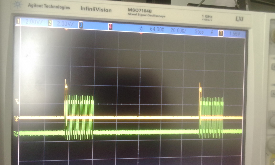
by youthreewire » Mon Aug 03, 2015 07:36 UTC
Now I am getting clean values. The problem was that the clock of the codec was at 11mhz and not at 5.5Mhz. Some how the clock was not getting set to 5.5Mhz although you mentioned earlier that that should be the clock.
by youthreewire » Mon Aug 03, 2015 08:44 UTC
I change to 16BIT SPI on the due and I am getting nice plots.
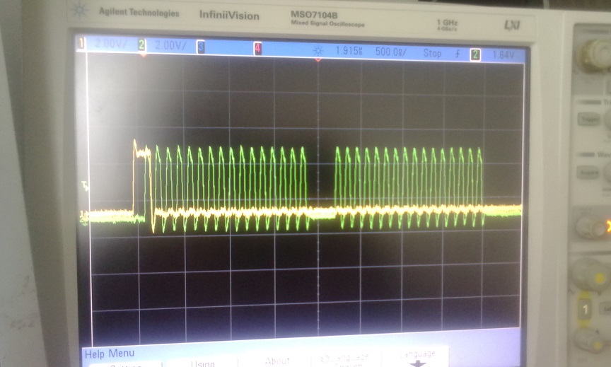
by guest » Mon Aug 03, 2015 18:04 UTC
excellent, glad its working. i will look into the 11MHz thing.
by guest » Mon Aug 03, 2015 18:06 UTC
also, have you tuned your scope probes? there seems to be a lot of ringing in those plots. it could be the circuit, or the probes. there should be a square wave source on the scope that you can connect the probe to, and then turn the small trimmer till the ringing goes away.
by youthreewire » Tue Aug 04, 2015 06:05 UTC
No I did not tune the probes but it is working great now. Thank you for your support.
by guest » Tue Aug 04, 2015 16:06 UTC
i checked my codecshield here, and its outputting a 5.5MHz clock to the microcontroller, and the clock settings are the same as yours, so im not sure what up with that.
by youthreewire » Wed Aug 05, 2015 06:17 UTC
One problem that I am facing right now is that I am getting frozen output.If I hit reset a couple of times then I am getting the actual values. What could be the problem? Should I reduce the ringing by using a 10pf capacitor. Where should I connect the capacitor? Between SCK and Ground and the other between SS pin and Ground?
by guest » Thu Aug 06, 2015 04:41 UTC
check it on the scope, and make sure the SPI is still behaving properly when its frozen. if so, then the problem is most likely the SPI interrupt getting out of sync (timer missing a count or interrupt being delayed). remove everything from your program that isnt absolutely neccessary, and see if it freezes (do a passthrough to verify its still running). then add things back in, one at a time, and see what makes it freeze.
by youthreewire » Thu Aug 06, 2015 17:16 UTC
Now I am planning to develop a library for intel edison.I will start a new thread.
by benbiles » Wed Jun 08, 2016 13:58 UTC
Hi, is there a working Library for Arduino DUE and the Audio Codec Shield ? The thread said solved but there is no link to a library ?
Thank, Ben
by guest » Thu Jun 23, 2016 21:28 UTC
sorry for the delayed response, the forums are mostly closed at this point.
take a look at some of the previous pages of this thread. there should be some code posted in there. im not sure its entirely functional code, but following the same clues i provided to youthreewire, you should be able to get it running as well. there is also some chance he was using the Mikro codec board, and not a codecshield.