Tools and Techniques for Musicians, Composers, and Tinkerers
Audio codec shield with Intel Edison
41 posts · 123576 views
by youthreewire » Thu Aug 06, 2015 17:24 UTC
Hello,
Greetings!
After developing a library successfully for the Arduino Due I am planning to extend the same to Intel Edison. So what functionality do we need? Edison does I2C, it can mimic timers and interrupts though actually it does not have them. I think I might have to see how to use an external clock signal to generate interrupts on the edison.
Apart from the external clock interrupt I dont see what problem there could be.Please pour in your suggestions.I will also start a thread in the edison forums.
Thanks
by youthreewire » Sat Aug 08, 2015 05:35 UTC
So what is the relation between the CLKOUT signal at 11 mhz from the the codec and the ISR at 44 khz. I mean how should the CLKOUT signal and SS pin wave together look like in the oscilloscope?
by guest » Sat Aug 08, 2015 18:32 UTC
i dont know anything about the edison, but i have a friend i can ask.
as for the clk_out, that should really be at 5.5MHz. its ok if its 11MHz, but the CK/2 bit should be set in the setup registers. the SS output and the clock signal should be synchronized with each other. ie, if you look at them on the scope, they should not move with respect to each other.
by youthreewire » Mon Aug 10, 2015 12:33 UTC
So when I am using SCL and SDA in I2C what among them is output or input. I think SCL might be output and SDA an input pin. Because in doing I2C communication I need to set the output and input pins. I will first try I2C with BYPASS enable and see if first I2C is working. Then I will code for ISR and timers and then SPI.
by youthreewire » Mon Aug 10, 2015 12:45 UTC
Just tested I2C, it is working and configuring the codec as needed.I will move onto interrupts,SS and SPI.
by youthreewire » Tue Aug 11, 2015 06:20 UTC
The question you might want to ask your friend is how do you track at external interrupt signal at 11Mhz/256 (for 44 Khz) and this timing should drive the ISR.
by youthreewire » Tue Aug 11, 2015 11:10 UTC
You told me in the past that the first pulse of SS should be aligned with the falling edge of SPI Clock. I understood that but now I want to know how should the SS pin wave be aligned to the 11Mhz or 5.5Mhz CLKOUT signal from the codec? Since I am not able to track the CLKOUT in edison I will try to read the moment when it is high and start the timer with respect to the rising edge of the CLKOUT signal. If align them this way at the beginning will it remain aligned for the rest of the time or should we see the RISING edge every time?Please let me know.
by youthreewire » Tue Aug 11, 2015 14:03 UTC
My code for Edison. I2C works and configures the codec right but SPI is still work in progress. Will debug this tomorrow using the scope
#include <TimerOne.h>
#include "SPI.h"
#include <Wire.h>
#define LINVOL 23
#define RINVOL 23
#define LHPVOL 100
#define RHPVOL 100
#define ADCHPD 0
#define SIDEATT 0
#define SIDETONE 0
#define DACSEL 1
#define BYPASS 0
#define INSEL 0
#define MUTEMIC 1
#define MICBOOST 0
#define SAMPLE_RATE 8
int myi=0;
bool ledon;
int temp_spi[4];
volatile unsigned int temp =0;

void AudioCodec_init() {


  // setup i2c pins and configure codec
  // the new Wire library has trouble with 0x00, so (uint8_t) is added
  // To change the Wire interface speed, go to:
  // <path_from_arduino>\hardware\arduino\sam\libraries\Wire\Wire.h
  // and change the parameters TWI_CLOCK, RECV_TIMEOUT and XMIT_TIMEOUT
  // to the desire frequency.
  int temp_wire1;
  int temp_wire2;

  Wire.begin();
  Wire.beginTransmission(0x1a);
  Wire.write(0x0c); // power reduction register
  Wire.write((uint8_t)0x00); // turn everything on
  temp_wire1 = Wire.endTransmission();

  Wire.beginTransmission(0x1a);
  Wire.write(0x0e); // digital data format
  Wire.write(0x03); // 16b SPI mode
  temp_wire2 = Wire.endTransmission();

  Serial.println(temp_wire1);
  Serial.println(temp_wire2);

  Wire.beginTransmission(0x1a);
  Wire.write((uint8_t)0x00); // left in setup register
  Wire.write((uint8_t)LINVOL);
  Wire.endTransmission();

  Wire.beginTransmission(0x1a);
  Wire.write(0x02); // right in setup register
  Wire.write((uint8_t)RINVOL);
  Wire.endTransmission();

  Wire.beginTransmission(0x1a);
  Wire.write(0x04); // left headphone out register
  Wire.write((uint8_t)LHPVOL);
  Wire.endTransmission();

  Wire.beginTransmission(0x1a);
  Wire.write(0x06); // right headphone out register
  Wire.write((uint8_t)RHPVOL);
  Wire.endTransmission();

  Wire.beginTransmission(0x1a);
  Wire.write(0x0a); // digital audio path configuration
  Wire.write((uint8_t)ADCHPD);
  Wire.endTransmission();

  Wire.beginTransmission(0x1a);
  Wire.write(0x08); // analog audio pathway configuration
  Wire.write((uint8_t)((SIDEATT << 6) | (SIDETONE << 5) | (DACSEL << 4) | (BYPASS << 3) | (INSEL << 2) | (MUTEMIC << 1) | (MICBOOST << 0)));
  Wire.endTransmission();

  Wire.beginTransmission(0x1a);
  Wire.write(0x10); // clock configuration
#if SAMPLE_RATE == 88
  Wire.write(0xbc);
#elif SAMPLE_RATE == 44
  Wire.write(0xa0);
#elif SAMPLE_RATE == 22
  Wire.write(0xe0);
#elif SAMPLE_RATE == 8
  Wire.write(0xac);
#elif SAMPLE_RATE == 2
  Wire.write(0xce);
#endif
  Wire.endTransmission();

  Wire.beginTransmission(0x1a);
  Wire.write(0x12); // codec enable
  Wire.write(0x01);
  Wire.endTransmission();

}

void setup()
{
  // Initialize the digital pin as an output.
  // Pin 13 has an LED connected on most Arduino boards
  //system("echo 40 > /sys/class/gpio/export");
   system("echo 128 > /sys/class/gpio/export"); //pin 2
  system("echo 42 > /sys/class/gpio/export");//pin  13
  system("echo in > sys/class/gpio/gpio128/direction");

   SPI.begin();  // Begin SPI hardware
   SPI.setBitOrder(MSBFIRST);
  SPI.setClockDivider(SPI_CLOCK_DIV16);
  SPI.setDataMode(SPI_MODE0);

  pinMode(2,INPUT);
  pinMode(12,OUTPUT);
  Serial.begin(9600);
  //Serial.begin(9600);
  Timer1.initialize(125); // set a timer of length 100000 microseconds (or 0.1 sec - or 10Hz => the led will blink 5 times, 5 cycles of on-and-off, per second)
  Timer1.attachInterrupt(timerIsr,CHANGE ); // attach the service routine here
  //attachInterrupt(2, pinChange, CHANGE);
}

void loop()
{
  if(fastGpioPciDigitalRead(2)==HIGH)
  {

   Timer1.attachInterrupt(timerIsr,CHANGE );

  }
  /*else
  //(fastGpioPciDigitalRead(2)==HIGH)
  {
  fastGpioPciDigitalWrite(13,LOW);
__asm__("nop");
  }*/

   Serial.print(temp_spi[0]);
   Serial.print(" ");
   Serial.print(temp_spi[1]);
   Serial.print(" ");
   Serial.print(temp_spi[2]);
   Serial.print(" ");
   Serial.print(temp_spi[3]);
   Serial.println(myi);}

void timerIsr()
{
    // Toggle LED
    fastGpioPciDigitalWrite(12,HIGH);
   __asm__("nop");
   myi++;

   temp = random(65535);
        temp_spi[0] = SPI.transfer(highByte(temp));
        fastGpioPciDigitalWrite(12,LOW);
        temp_spi[1] = SPI.transfer(lowByte(temp));
        temp_spi[2] = SPI.transfer(highByte(temp));
        temp_spi[3] = SPI.transfer(lowByte(temp));


}
by guest » Tue Aug 11, 2015 19:09 UTC
i asked my friend about the edison, and he said it doesnt have any hardware timers that are usable. im not sure how interrupts even work on it. you could put an external counter chip on, but it ultimately may not work. the codecshield is set to work in slave mode, which is not very conducive to most larger platforms. with the edison you can just put a usb sound card on it.
with the master clock and SS signals, i dont think it matters whether its aligned to rising or falling edge, just as long as its consistent.
by youthreewire » Wed Aug 12, 2015 04:31 UTC
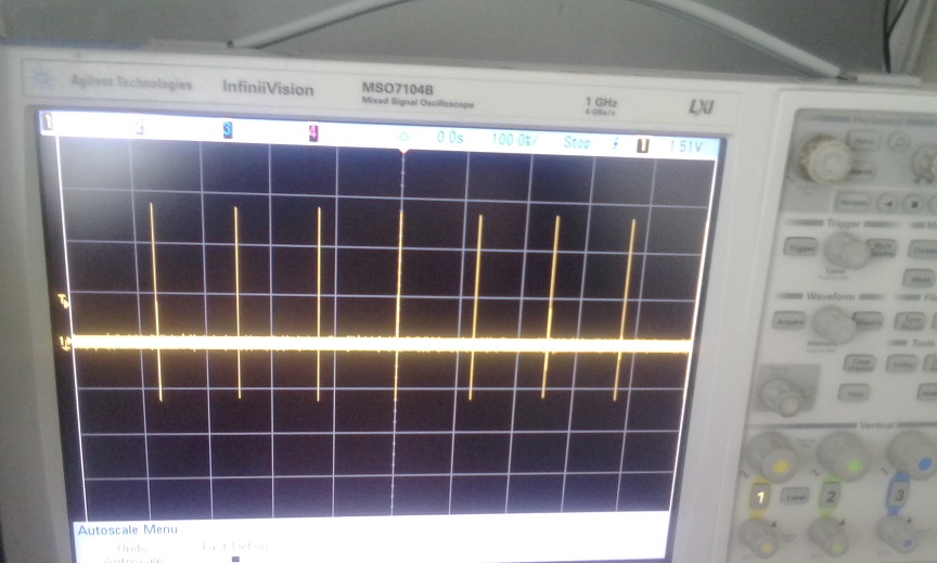
Software emulation of timers and interrupts is there on edison.I am able to get an 8khz interrupt on the edison.Here is the scope shot:
by youthreewire » Wed Aug 12, 2015 17:10 UTC
I generated 8khz,4khz and 2 khz waves on a pin and gave it as interrupt to another pin and the ISR is able to work at these frequencies. So what shall I do now and how important is the 11mhz signal from the CLKOUT pin of the codec. How do I sync my 8khz wave with the 11mhz signal. Should I use additional hardware like counters or some other ICs etc. Please guide me on this. The good news is that the ISR can work at 8khz.
by guest » Wed Aug 12, 2015 19:04 UTC
an external counter would be the easiest thing. if the edison can accept 3.3V logic signals in, then something like a 74HC4040 would be fine.
by youthreewire » Thu Aug 13, 2015 03:08 UTC
But even if we are able to catch the interrupt at 8khz or 4khz or 2Khz we will have to synch it with the SPI clock. The high level SPI.Transfer function in the edison is inducing delay. We will be needing access to the bare metal code of the edison to sync the SPI transfers.I have asked for the bare metal code in the edison forum but I do not know if they will provide me.
by youthreewire » Thu Aug 13, 2015 03:13 UTC
I have never used a counter earlier. So how does this work?Instead can we use the arduino as the counter IC? Edison arduino board can accept 3.3V and even 5v. I think it should be possible as the ISR already does that.
by guest » Thu Aug 13, 2015 18:15 UTC
sure, you can use the arduino as a counter, just take the old SS signal out and send it to the interrupt on the edison. the delay probably wont be a problem, as long as its a consistent delay (the exact same amount every time).
by guest » Wed Sep 02, 2015 19:33 UTC
somone else has been working on this as well, and have the DAC functioning:
http://www.malinov.com/Home/sergey-s-bl ... odecshield
im skeptical that it is a robust solution, as it operates the codec in slave mode, but does not supply a clock. but it is working.
by youthreewire » Fri Sep 18, 2015 05:01 UTC
But how will get access to lin,rin and lout and rout. I tested the codec configuration with I2C by just using BYPASS.My code works but I have not been able to get the I2S/SPI working (there is too much clock cycle delay). So now if I follow sergey's setup how will I get access to lin,rin and lout,rout?
by youthreewire » Fri Sep 18, 2015 05:43 UTC
I think I will have to look into alsa programming. So do you know about a sample code to capture and playback like one of your arduino examples with the shield?
by youthreewire » Fri Sep 18, 2015 05:58 UTC
I came across this loopback program but it does not say anything about lout,lin and rout,rin.
https://github.com/zonque/simple-alsa-l ... ter/loop.cby youthreewire » Fri Sep 18, 2015 09:32 UTC
In which forum should I post the questions on ALSA?
by youthreewire » Fri Sep 18, 2015 10:17 UTC
by youthreewire » Thu Nov 05, 2015 04:07 UTC
Hello,
I came across a software SPI library recently.I want to use this in the Due. Earlier I used SPI like this:
while((SPI0->SPI_SR & SPI_SR_TDRE)==0)
 {;}

  while ((SPI0->SPI_SR & SPI_SR_TXEMPTY) == 0);
  digitalWriteDirect(12, HIGH);
 SPI0->SPI_TDR = rout;
   //SPI0->SPI_TDR = lout;
  __asm__("nop");
  __asm__("nop");
  __asm__("nop");
  __asm__("nop");
  __asm__("nop");
  __asm__("nop");
  __asm__("nop");
  __asm__("nop");
  __asm__("nop");
  __asm__("nop");
  __asm__("nop");

 digitalWriteDirect(12, LOW);

 while((SPI0->SPI_SR & SPI_SR_TDRE)==0)
 {;}

 while((SPI0->SPI_SR & SPI_SR_RDRF) == 0)
 {;}
 lin = SPI0->SPI_RDR;
 delayMicroseconds(1);
  while((SPI0->SPI_SR & SPI_SR_RDRF) == 0)
 {;}
 rin = SPI0->SPI_RDR;
I am doing 16 bit SPI transfers.I want to do the same with the software SPI here.
http://www.iesensor.com/blog/2013/07/09/software-spi-library-for-arduino-tested-on-mega2560/
#include <stdint.h>
    #define _MISO  40
    #define _MOSI  41
    #define _SCK   42
    #define _SS  12

    #define _CPOL 0
    #define _CPHA 1

    #define SPI_MSBFIRST 1

    uint8_t spi_transfer(uint8_t b) ;
    void spi_setup();

    //#if  1//defined(__AVR_ATmega2560__)
      //for example 8cycles as one SPI period, for Arduino mega2560 16MHz, SPI 2MHz,  tested passed for AD7730!
      //for DUE 84MHz,  need longer nop cycles to keep waveform!  -> multiply each delay by 6
      #define DELAY_CYCLES  2     //more precise than micro second delay,  1/4 of SPI bus frequency , depends on MCU master clock,
      #define DELAY_CYCLES_P0  1  //propogation pre
      #define DELAY_CYCLES_P1  3  //propogation post
      #define DELAY_CYCLES_C0 1   //capture pre (SCK edge -> capture) usually smaller delay
      #define DELAY_CYCLES_C1 3   //capture post ( capture -> SCK edge)  usually bigger delay
    //#else
    //  #error "checking your board and MCU main frequency and set prooper delay for software_SPI bit-banging"
    //#endif

 // #endif


  /*
  The timing diagram is shown to the right. The timing is further described below and applies to both the master and the slave device.

      At CPOL=0 the base value of the clock is zero
          For CPHA=0, data is captured on the clock's rising edge (lowâ†'high transition) and data is propagated on a falling edge (highâ†'low clock transition).
          For CPHA=1, data is captured on the clock's falling edge and data is propagated on a rising edge.  ->  MODE1 for Arduino SPI lib
      At CPOL=1 the base value of the clock is one (inversion of CPOL=0)
          For CPHA=0, data is captured on clock's falling edge and data is propagated on a rising edge.
          For CPHA=1, data is captured on clock's rising edge and data is propagated on a falling edge.
  */

//#endif // header

//if SOFTWARE_SPI

  static inline void delayCycles(int cycles)
  {
      for (int i=0; i++; i<cycles)
          __asm__("nop\n\t");
         // __nop();
  }


  //#if SPI_MSBFIRST
    unsigned char msk[] = {0x80, 0x40, 0x20, 0x10, 0x8, 0x4, 0x2, 0x1};
    #define PCK() (bits[0] << 7 | bits[1] << 6 | bits[2] << 5 | bits[3] << 4 | bits[4] << 3 | bits[5] << 2 | bits[6] << 1 | bits[7])
  //#else
    //unsigned char msk[] = {0x1, 0x2, 0x4, 0x8, 0x10, 0x20, 0x40, 0x80};
    //#define PCK() (bits[0]  | bits[1] << 1 | bits[2] << 2 | bits[3] << 3 | bits[4] << 4 | bits[5] << 5 | bits[6] << 6 | bits[7]<<7)
 // #endif


  void spi_setup()
  {
    pinMode(_SS, OUTPUT);
    pinMode(_MISO, INPUT);
    pinMode(_MOSI, OUTPUT);
    pinMode(_SCK, OUTPUT);
    //
     digitalWrite(_SS, HIGH);
    #if _CPOL
     digitalWrite(_SCK, HIGH);
    #else
     digitalWrite(_SCK, LOW);
    #endif
  }

  // chip selection has been declared outside
  inline void spi_select() {digitalWrite(_SS, LOW);}
  inline void spi_unselect() {digitalWrite(_SS, HIGH);}

  //mode 0: SCK idle low, phase: reading at middle of SCK HIGH pulse
  //mode 1: SCK idle low, phase: reading at middle of SCK LOW pulse
  //this big-bang should work for both  CPHA=1  and CPHA=0
  uint8_t spi_transfer(uint8_t b)
  {
    uint8_t reply=0;
    char bits[8] = {0, 0, 0, 0, 0, 0, 0, 0};  //reading buffer

    /*  hardware SPI
    SPDR=b;
    spi_wait();
    reply = SPDR;
    return reply;*/

      //cli();  it will cause error on Arduino, most of SPI should be interrupt tolerable
      //spi_select(); // should be called outside, may be required by one transition
      delayCycles(DELAY_CYCLES);   // checking timing characteristics, need delay from CS to rising edge?
      // here, delay is added, to make CPHA=1 and CPHA=0 both work!

      for(uint8_t _bit = 0;_bit < 8;_bit++)
      {
      #if _CPHA
        #if _CPOL
          digitalWrite(_SCK, LOW);  //  propagation at rising edge
       #else
          digitalWrite(_SCK, HIGH);  // change this to LOW for CPOL=1
       #endif
          digitalWrite(_SCK, HIGH);  // change this to LOW for CPOL=1
          delayCycles(DELAY_CYCLES_P0);

          digitalWrite(_MOSI, !!(b & msk[_bit]));
          delayCycles(DELAY_CYCLES_P1); //  propagation
       #if _CPOL
         digitalWrite(_SCK, HIGH);  // data will be captured at falling edge
       #else
          digitalWrite(_SCK, LOW);
       #endif
         delayCycles(DELAY_CYCLES_C0); // holding low, so there is enough time for data preparation and changing

         bits[_bit] = digitalRead(_MISO); // reading at the middle of SCK pulse
         delayCycles(DELAY_CYCLES_C1);  // wait until data is fetched by slave device,  while SCK low, checking DATAsheet for this interval

      #else
          // changing MOSI big while SCK low, propogation
          digitalWrite(_MOSI, !!(b & msk[_bit]));
          delayCycles(DELAY_CYCLES_P1); // there is a requirement of LOW and HIGH have identical interval!

        #if _CPOL
         digitalWrite(_SCK, LOW);
        #else
         digitalWrite(_SCK, HIGH);
        #endif
         delayCycles(DELAY_CYCLES_C0);    //

         bits[_bit] = digitalRead(_MISO); // reading at the middle of SCK pulse
         delayCycles(DELAY_CYCLES_C1);  // wait until data is fetched by slave device,  while SCK high, checking DATAsheet for this interval

        #if _CPOL
          digitalWrite(_SCK, HIGH);
        #else
         digitalWrite(_SCK, LOW);  // data will change at falling edge
        #endif
         delayCycles(DELAY_CYCLES_P0); // holding low, so there is enough time for data preparation and changing

      #endif

      }
     delayCycles(DELAY_CYCLES);  // checking timing characteristics, it is no needed by AD7730, from CS to rising edge
     // spi_unselect();

      //sei();  // it will cause error on Arduino, most of SPI should be interrupt tolerable

     reply = PCK();

    return reply;

  }

//#endif

uint8_t temp1;
void setup( )
{
  spi_setup( );
}

void loop( )
{
  spi_transfer(temp1);
}
How shall I do it?
by guest » Thu Nov 05, 2015 16:15 UTC
what doesnt work about the software SPI library? you will probably have to change how the SS pin operates
by youthreewire » Fri Nov 13, 2015 06:41 UTC
I was able to get the software SPI (i.e SCK pin wave) sync with the SS pin wave at the first bit.I will see if I am getting any sound from the codec at this point and then will later try and replicate the same in edison.
by youthreewire » Fri Nov 20, 2015 07:33 UTC

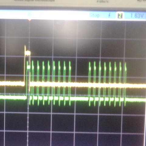
The above are my oscilloscope shots for the SS pin (yellow) and SCK pin(green).The first SCK pulse is actually little wider in width.Will it work?
by guest » Fri Nov 20, 2015 18:50 UTC
looks good, should work
by youthreewire » Wed Nov 25, 2015 10:16 UTC
Software SPI is working on the Due . Now I will try and replciate it on the edison.
by youthreewire » Wed Dec 02, 2015 04:03 UTC
The earlier result is not a true result because the "bypass" flag was set to 1.The following is my ISR function which runs at 44 khz or 8khz (as per the specified frequency).
void TC8_Handler()
{
 ledon1 = !(ledon1);
 digitalWrite(13, ledon1);

  linh = spi_transfer(lout>>8,1);
  linl = spi_transfer(lout,2);
 lina[myi]=(linh << 8)|(linl & 0xff);
}
All I get is a cracking sound. I do not know if I am doing it right with the bit shifts and SPI transfers
by guest » Wed Dec 02, 2015 18:43 UTC
looking at your picture again, there are 9 pulses on the first transfer. there should only be 8.
by youthreewire » Thu Dec 03, 2015 04:29 UTC
Yea I corrected the 9 pulses thing to 8. But still I get crackling sound. I wonder what is wrong.Is the folowing piece of code right?
void TC8_Handler()
{
  linh = spi_transfer(lout>>8,1);
  linl = spi_transfer(lout,2);
 lina[myi]=(linh << 8)|(linl & 0xff);
}
Can you implement the same software SPI on your arduino (it should run on atmega328 arduino as well) and let me know.I will then port it to Due and Edison.
by guest » Thu Dec 03, 2015 06:44 UTC
that code may not work, depending upon how youve defined the variables, it might lose the sign bit (which sounds like crackling). a good test is to create a signed 16b integer, and increment its value by 1 each time you write to the codec. the output should look like a saw tooth wave. if it does not, the shape it forms can tell you something about where the error is occuring (as longs as its not just noise). the frequency is really low at a +1 increment, so try +100 if youre not probing the DC coupled output (or just want to listen to it).
by youthreewire » Fri Dec 04, 2015 14:07 UTC
Could you please try the software SPI code on one of your arduinos with the shield and guide me?Please.... Here is the link to software SPI. I changed the code of the transfer function further.
my transfer function is like this
uint8_t spi_transfer(uint8_t b,uint8_t uu_firstbyte)
  {
    uint8_t reply=0;
    char bits[8] = {0, 0, 0, 0, 0, 0, 0, 0};  //reading buffer

      for(uint8_t _bit = 0;_bit < 8;_bit++)
      {
        if(uu_firstbyte==1 && _bit==0)
        {
        digitalWriteDirect(11, HIGH);
        __asm__("nop");
         __asm__("nop");
         __asm__("nop");
        digitalWriteDirect(_SCK, HIGH);
         __asm__("nop");

         bits[_bit] = digitalReadDirect(_MISO);
         digitalWriteDirect(_MOSI, !!(b & msk[_bit]));
         digitalWriteDirect(11, LOW);
         digitalWriteDirect(_SCK, LOW);
        }

        if((_bit>=1)||(uu_firstbyte==2))
        {
         bits[_bit] = digitalReadDirect(_MISO);
         digitalWriteDirect(_MOSI, !!(b & msk[_bit]));
       digitalWriteDirect(_SCK, HIGH);
        __asm__("nop");
         //__asm__("nop");
         //__asm__("nop");
         //__asm__("nop");
         //__asm__("nop");
       digitalWriteDirect(_SCK, LOW);
        }
      }

      reply = PCK();

    return reply;


      }

  }
The reason I think this is important is that once the software spi gets working we can extend it to any other microcontroller or processor board and the shield will be free from hardware spi dependency.
by guest » Fri Dec 04, 2015 21:41 UTC
sure, i can give it a try, but it might be a while. did you have any luck getting it working on your end?
also, how long a "nop" is, is hardware dependent. on some platforms it might make the SPI too fast.
by youthreewire » Sat Dec 05, 2015 07:48 UTC
Thanks. Please give it a try.
I am running the code on Arduino Due which is overclocked at 96 mhz. So as you rightly said nop will introduce different timing. You will be needing an oscilloscope that can measure in nano seconds (my scale was that one division on the scope was 200 nanoseconds long).I tried changing the values to match with the hardware spi that I got to work on the Due.
I will wait for the results from your end on the software SPI. You know better about timing.
Here is the link to the original software SPI .
http://www.iesensor.com/blog/2013/07/09/software-spi-library-for-arduino-tested-on-mega2560/by guest » Mon Dec 07, 2015 23:12 UTC
do you have a complete sketch i can test? im not sure what 'b' or msk[] are referring to.
by youthreewire » Wed Dec 09, 2015 06:15 UTC
I will give you the sketch and I think as you said I should test with an unsigned 8 bit integer.I will get back to you shortly.
by youthreewire » Fri Dec 11, 2015 07:35 UTC
Here is the sketch.It compiles but there could be a logical error
// setup codec parameters
    // must be done before #includes
    // see readme file in libraries folder for explanations
    #define SAMPLE_RATE 44 // 44.1Khz
    #define ADCS 0 // no ADCs are being used

    // include necessary libraries
    #include <Wire.h>
    #include <SPI.h>
    #include <AudioCodec.h>
    #include <digitalWriteFast.h>
   #define _MISO  8
    #define _MOSI  9
    #define _SCK   10
    #define _SS  11
    #define PCK() (bits[0] << 7 | bits[1] << 6 | bits[2] << 5 | bits[3] << 4 | bits[4] << 3 | bits[5] << 2 | bits[6] << 1 | bits[7])
    unsigned char msk[] = {0x80, 0x40, 0x20, 0x10, 0x8, 0x4, 0x2, 0x1};
   // #define PCK() (bits[0] << 7 | bits[1] << 6 | bits[2] << 5 | bits[3] << 4 | bits[4] << 3 | bits[5] << 2 | bits[6] << 1 | bits[7]);

    // create data variables for audio transfer
    int left_in = 0x0000;
    int left_out = 0x0000;
    int right_in = 0x0000;
    int right_out = 0x0000;
uint8_t spi_transfer(uint8_t b,uint8_t uu_firstbyte)
  {
    uint8_t reply=0;
    char bits[8] = {0, 0, 0, 0, 0, 0, 0, 0};  //reading buffer

      for(uint8_t _bit = 0;_bit < 8;_bit++)
      {
        if(uu_firstbyte==1 && _bit==0)
        {
        digitalWriteFast(11, HIGH);
        __asm__("nop");
         __asm__("nop");
         __asm__("nop");
        digitalWriteFast(_SCK, HIGH);
         __asm__("nop");

         bits[_bit] = digitalReadFast(_MISO);
         digitalWriteFast(_MOSI, !!(b & msk[_bit]));
         digitalWriteFast(11, LOW);
         digitalWriteFast(_SCK, LOW);
        }

        if((_bit>=1)||(uu_firstbyte==2))
        {
         bits[_bit] = digitalReadFast(_MISO);
         digitalWriteFast(_MOSI, !!(b & msk[_bit]));
       digitalWriteFast(_SCK, HIGH);
        __asm__("nop");
         //__asm__("nop");
         //__asm__("nop");
         //__asm__("nop");
         //__asm__("nop");
       digitalWriteFast(_SCK, LOW);
        }
      }

      reply = PCK();

    return reply;


  }
    void setup() {
      Serial.begin(115200);
      AudioCodec_init(); // setup codec registers
      // call this last if setting up other parts
    }

    void loop() {
      //Serial.println(left_in); // reduces clock jitter

    }

static inline void AudioCodec_data2(int _lin, int _rin, int _lout, int _rout)
{ _lout= spi_transfer(_lin,1);
  _rout = spi_transfer(_rin,2);

}
// timer1 interrupt routine - all data processed here
    ISR(TIMER1_COMPA_vect) { // NAKED turned off, so registers are stored
      AudioCodec_data2(left_in, right_in, left_out, right_out);
      left_out = left_in;
      right_out = right_in;
      //Serial.println(left_in);
      //reti(); // dont need this without NAKED
    }
by guest » Fri Dec 11, 2015 22:52 UTC
what failure mode do you see with this code?
a couple of things to note:
1. you can not send audio data over the serial comm, the audio data rate is too high
2. hardware spi is still being setup with codec.h, which is probably conflicting with direct port manipulation.
by youthreewire » Sat Dec 12, 2015 11:19 UTC
I know that the audio data cannot be sent over the serial port. Also I just made this sketch for you.I was using an ARDUINO Due and since you had atmega328 I just wrote this code up.Feel free to modify as you want it.
I also created a 6 MBPS transfer rate on the Due but still it had some delay.
by guest » Mon Dec 14, 2015 05:14 UTC
i gave it a try, and sadly it does not work. here is my code:
// setup codec parameters
// must be done before #includes
// see readme file in libraries folder for explanations
#define SAMPLE_RATE 44 // 44.1Khz
#define ADCS 0 // no ADCs are being used

// include necessary libraries
#include <Wire.h>
#include <SPI.h>
#include <AudioCodec.h>
#include <digitalWriteFast.h>
#define _MISO  12
#define _MOSI  11
#define _SCK   13
#define _SS  10
#define PCK() (bits[0] << 7 | bits[1] << 6 | bits[2] << 5 | bits[3] << 4 | bits[4] << 3 | bits[5] << 2 | bits[6] << 1 | bits[7])
unsigned char msk[] = {0x80, 0x40, 0x20, 0x10, 0x8, 0x4, 0x2, 0x1};

// create data variables for audio transfer
int left_in = 0x0000;
int left_out = 0x0000;
int right_in = 0x0000;
int right_out = 0x0000;

uint8_t spi_transfer(uint8_t b,uint8_t uu_firstbyte) {
  uint8_t reply=0;
  char bits[8] = {0, 0, 0, 0, 0, 0, 0, 0};  //reading buffer
  for(uint8_t _bit = 0;_bit < 8;_bit++) {
    if(uu_firstbyte==1 && _bit==0) {
      digitalWriteFast(_SS, HIGH);
 //     __asm__("nop");
 //     __asm__("nop");
 //     __asm__("nop");
      digitalWriteFast(_SCK, HIGH);
 //     __asm__("nop");
      bits[_bit] = digitalReadFast(_MISO);
      digitalWriteFast(_MOSI, !!(b & msk[_bit]));
      digitalWriteFast(_SS, LOW);
      digitalWriteFast(_SCK, LOW);
    }
    if((_bit>=1)||(uu_firstbyte==2)) {
      bits[_bit] = digitalReadFast(_MISO);
      digitalWriteFast(_MOSI, !!(b & msk[_bit]));
      digitalWriteFast(_SCK, HIGH);
 //     __asm__("nop");
      digitalWriteFast(_SCK, LOW);
    }
  }
  reply = PCK();
  return reply;
}

void setup() {
  AudioCodec_init(); // setup codec registers
  SPI.end(); // disable hardware SPI
  pinMode(_SS, OUTPUT);
  pinMode(_SCK, OUTPUT);
  pinMode(_MOSI, OUTPUT);
  pinMode(_MISO, INPUT);
}

void loop() {
}

// timer1 interrupt routine - all data processed here
ISR(TIMER1_COMPA_vect) {
  left_in = spi_transfer(left_out,1);
  right_in = spi_transfer(right_out,2);
  left_out = left_in;
  right_out = right_in;
}
one major error is that its only transferring 16b per frame, rather than the required 32b (L+R), but that isnt the limiting factor right now. the speed of the spi-transfer function is just too slow. i may have loaded the wrong digitalwritefast library, but if even so, there probably isnt one that works any faster. the issue is that most are going to use a function call rather than inlining the code. they will probably also try to replicate the pwm override capability. both of these things slow it down to an unusable state. another issue is that any digitalread will be too slow. it takes at least 2 clocks of setup before an input pin is stabilized to read. multiply that by the 32b required is a minimum of 64 clock cycles of just waiting.
the fastest possible, using inline assembly and knowing ahead of time which pins you were using, and unrolling the loop would take around 6 clock cycles per bit, which is 2/3rds of the total time available at 44ksps. there wouldnt be time left over to do much else.
by youthreewire » Mon Dec 14, 2015 08:53 UTC
I tried the code on Due and the pin up and down for SCK and SS pin are fast. I used direct port manipulation in the Due code.I will also try the SPI transfer with the Atmega328 and post the results to you as early as I get my hands on the oscilloscope.