Board index › Projects › Floppy Audio Project

getting to know your read/write heads

39 posts · 144169 views

getting to know your read/write heads

by mcanulty » Mon Jan 17, 2011 04:51 UTC
This is a long time coming, I've been in the process of finishing an MFA program at Mills and it sucked up all of my time last term. While I've still got a few days I dusted off some folders and made some images for the floppy audio tutorial. Thought I'd get a start here and then move it over to more organized locations later.

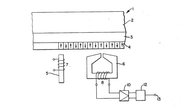
Here's an image I found in a patent for an r/w head:
image
It's from US Patent 4,251,842 - Magnetic Recording and Reproducing Device

That gives you the basic idea of what's going on, (ignoring 7 and 5 for now) there's a coil for inducing a magnetic field and a bit of metal for directing that field across a gap which will then organize the magnetic material on whatever media it's traversing. And it works both ways, the magnetic media can induce an alternating current in the metal which gets translated to the coil and back out to where we can hear it.

______________________________________________________

Now, if you look closely at your own floppy drive, you should be able to locate the head.

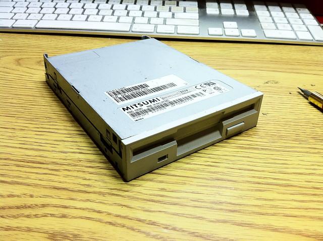
1. Here's a random drive I just happen to have lying around (I have a lot of them for some reason :)
image

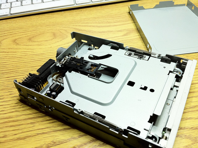
2. Each drive and drive manufacturer was different, so the covers and cases are all secured differently. Here's that Mitsumi with the cover removed:
image

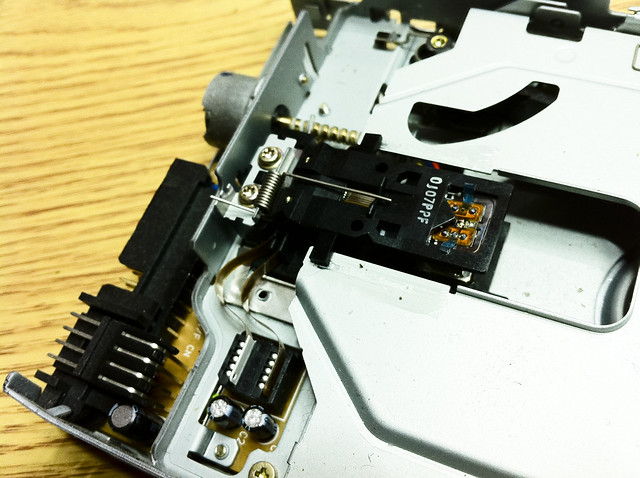
3. The two head arms are designed to squeeze the doublesided 3.5 inch diskette and sandwich it between the read/write heads. Two separate ribbon cables come out of the arms, one for each head.
image

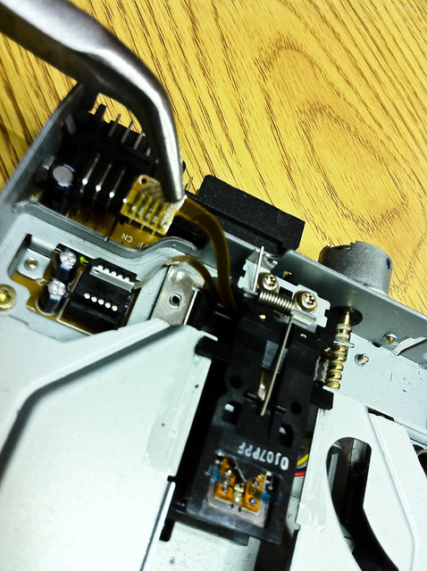
4. Pardon the blurriness here, but having removed one of the ribbon cables you can see that there are more than two connections per head, in fact there are five different contact points.
image


______________________________________________________

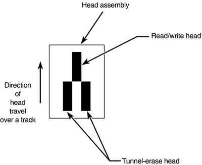
So why five contact points? This is so that the heads could do something called "tunnel erase", basically trimming the edges of a data write in order to keep the tracks from bleeding into each other on the disk and corrupting the data.

With a graphic I found on page 647 of Scott Mueller's "Upgrading and Repairing PCs"
http://books.google.com/books?id=E1p2FDL7P5QC&lpg=PA646&ots=M1tlzb70fC&pg=PA647#v=onepage&q&f=false

you can picture the head looking like something like this:
image

Personally, I'm pretty sure that this bleeding across tracks is partly what's responsible for the cool sound that happens when you use the system to write audio, so needless to say we don't really have to worry about it too much. However, to get more familiar with the head, let's take a look at those 5 connections.

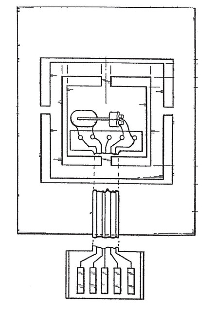
Here's a cool graphic I found in another patent:
image
from European Patent Application #82104726.3

Notice how one of the connections doesn't seem to be going to anything? That's actually connected to the shield, which can come in handy later. In this diagram it's the middle connector, that won't necessarily be the case in your floppy drive.

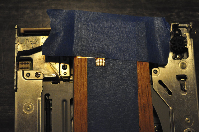
In order to figure out what's what, you should take out your multimeter and start probing the leads. It can be a pain to probe the leads on the tiny flex cable, so you can try a trick that I figured out at some point which was to tape the cable down. That way you're not too likely to rip it and it will help a ton when you want to probe it or solder it later.

This is a photo of one of the half height TEAC drives that I did my project with, those things were tiny!
image

When you take out your multimeter to probe the connections, you will find one that has a very large resistance from the others (that's the shield line) but you may be surprised to find that all of the other lines are virtually shorted to each other. In reality they have a very small resistance, but they are all connected.

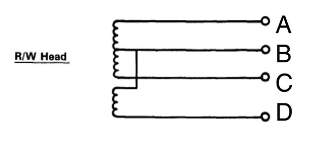
Trying to figure out what was going on with the head made a lot more sense when I discovered this diagram in a Commodore 64 manual:
image

Back when it was worth trying to fix floppy drives they provided this diagram and gave the proper resistance for each coil and how they should look when you were probing each section. I went ahead and labeled these since you'll have to figure out what part is which on your own.

A couple of useful observations: The resistance between A and C should be the same as the resistance between A->B and B->C added together. or:
A->C = (A->B) + (B->C)
also:
A->D = (A->B) + (B->D)
and:
C->D = (C->B) + (B->D)

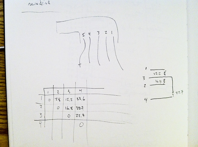
I made a little chart for each head I was working on and then labeled each connection so that I would know what it should look like. It doesn't have to be pretty, this is how mine looked:
image

Positioning a probe on line 1 (as drawn on the page), I measured and recorded the resistance between 1 and each of the other non-shield lines. Then I did the same with 2 and 3. I drew out the diagram found in the commodore manual and did the algebra by intuition. The two smallest figures conveniently add up to the resistance between 1 and 2, which leaves only 4 standing on its own. If memory serves each floppy drive I discovered followed this pinout, but it's fun to draw the little diagrams and it makes you feel good.

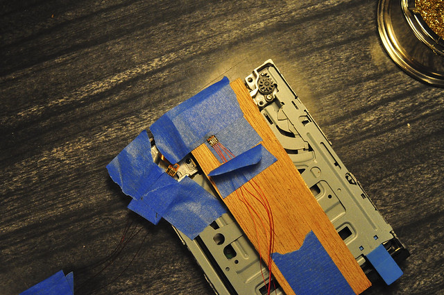
Once you've got it all figured out, you can either pick two and solder them up, or solder up all 5 and pick later. Don't forget to wire up the shield as well. If you have trouble soldering regular wires to the small connectors, you can try magnet wire. That worked really well for me:
image

I taped them all down and then soldered them one by one.

Okay I have to run for now, but more to come soon. Let me know if anyone has any questions!

Re: getting to know your read/write heads

by mcanulty » Mon Jan 17, 2011 10:02 UTC
updated the post with tunnel erase data. next topic to write up is digital control I think.

Re: getting to know your read/write heads

by StatiK » Mon Jan 17, 2011 18:07 UTC
wonderful ifnormation. I must admit im impressed with the level of research you have done. But this has given me the motivation to locate and rip apart a floppy, looking forward to more info!

Re: getting to know your read/write heads

by aelginfluensa » Fri Mar 11, 2011 09:20 UTC
Hi

Thanks a lot for the great info! I never understood which output/input was to the tape heads before.. Circuit girl's video is very inspiring but not very easy to follow..

Another thing I haven't figured out: how do I power up the motor? Can I use a battery or do I have to dig into another computer to get cables?

Re: getting to know your read/write heads

by mcanulty » Wed Mar 16, 2011 05:12 UTC
The motor can be powered with the same power as the rest of the drive. A battery probably wouldn't last very long, I would use some kind of power supply. I personally used an ATX power, if you want to make it general purpose I used a tutorial like this one:
http://www.wikihow.com/Convert-a-Computer-ATX-Power-Supply-to-a-Lab-Power-Supply

But you don't have to do anything to it necessarily. Just turn it on and plug in the drive.

Let me know if that helps!

Re: getting to know your read/write heads

by lazart » Fri May 13, 2011 21:25 UTC
hi,
found this fantastic project, that's probably be the best analog delay ever :) nothing new for two months?
I'm wondering how you managed it to read and write, or play and record sound at the same time? did you just use the r/w-heads on both sides? is the signal getting to the other side of the disk?

Re: getting to know your read/write heads

by mcanulty » Mon May 16, 2011 02:51 UTC
Hi lazart! I just finished an MFA in electronic music at Mills College on Friday, and the past two terms have had me a lot busier than I had imagined. But I'm getting my breath back and always am hoping to be more active about posting more material.

I had issues using both read heads, so for a continuous delay I had to use multiple drives, that was the really hard bit for me actually, trying to get the analog stuff to work right when I was a little inexperienced in that area. But I learned a lot and it worked!

When trying to use both sides, I found that the opposite read head would just electromagnetically couple with the other write head, so I was blasting the audio into the other head which made it kind of useless. It might be possible if you can write at low enough volumes, but on the other hand it might just be a physical limitation of the system.

Re: getting to know your read/write heads

by lazart » Wed May 18, 2011 23:18 UTC
Hi mcanulty,
Hope you'll get back a lot of breath soon :)
I thought about using the part of the head for tunnel erase to write and erase with an attached magnet, but maybe they'll also couple.
There also seems no way to get one head a bit away from the other. I got only one floppy drive that might be broken, can't get it to work but maybe I'm doing something wrong with the controlling.
Found this link http://www.epanorama.net/circuits/diskstepper.html which may be useful for someone here?

Re: getting to know your read/write heads

by aelginfluensa » Sat Jun 04, 2011 20:12 UTC
More patrol..

I did some soldering on one of the head connectors today, probably the hardest solding I ever did.. But I think I got them pretty good after a while. To which connections shall I connect the cables from the tape deck? I tried a few different combinations but all I heard was humming. But I don't what's on the floppy I tried with either..

Re: getting to know your read/write heads

by mcanulty » Mon Jun 06, 2011 03:58 UTC
Hey, glad to hear you're making progress! I experimented a bunch and found they all work pretty much the same. Just pick one coil and write to it using an amplifier. Basically drive the coil like it's a speaker. Start with a low volume, but on the bright side, if you burn it out you have other coils that you can use! After you've written some audio, listen back to it. The data on the disk won't sound like very much, it's not really written loudly enough to be heard over the hum of the drive anyway. But once you've written audio onto the diskette, you should be able to hear it with the lines coming from the tape recorder.

Dan

Re: getting to know your read/write heads

by cosmochaos » Mon Jun 06, 2011 12:23 UTC
Hello,

i am not familiar with the electronics but based on the post of this forum I achieved to control the spepper (using an arduino board) and to spin the motor! Now i want to read from and write on the floppy disk. I wired the floppy head but I don't know which of 5 wire wires are going where! I am waiting for your reply!
(Sorry for my bad english)

Thank you
dimitris

Re: getting to know your read/write heads

by mcanulty » Wed Jun 08, 2011 04:37 UTC
Hi Dimitri, you can try to follow the diagrams in the earlier post in this category, or you can just pick two and give it a shot. I'd say pick two of the inner ones and you should have a good chance to being able to read and write. Let me know how it turns out!

Re: getting to know your read/write heads

by cosmochaos » Tue Jun 14, 2011 13:46 UTC
Dear Dan,

Thank you very much for your reply.
I recorded on floppy by mistake! I can playback the recorded data using 2 and 3 wires.
Do I have to use the same wires for recording?
I would like to use it with a guitar.
Any ideas of how can I improve the sound quality?

Thank you again,
dimitris

Re: getting to know your read/write heads

by mcanulty » Wed Jun 15, 2011 06:57 UTC
So far I've had to use the same wires, so I set up a system with multiplexers and stuff to use three different drives. If I find a better method I will write about it! As far as audio quality, you can always try changing the loudness of how you write it, maybe more loud or less loud is better. And for reading off, I made my own amplifier system, and I'm thinking of trying a new system for the next version though that might get rid of the RF interference.

Re: getting to know your read/write heads

by mitcho » Thu Sep 08, 2011 01:02 UTC
Hello!
I need some help to get the audio signal recorded on the floppy. I drive the audio signal directly into the r/w head through the 2. and 3. wire and also tried with the 1. and 2. on another floppy drive. I chose those because they have the lowest resistance in between (4ohm - 14ohm), similar to the resistance of the speaker (8ohm) of the amplifier that I use to drive the signal. I tried with a low signal and slowly raised the loudness throughout the recording. When I read from the head I connect the same wires from the r/w head to my PC's mic input and boost it as much as I can, but nothing but noise comes out. I noticed that since I've soldered the wires on the r/w head between the 5th wire, the one that should go to GND, and the others there's around 140K ohm of resistance instead of infinite. I don't think this should be the problem. What should I try now?
Thanks a lot for this forum and all the information you're providing.

Re: getting to know your read/write heads

by mitcho » Thu Sep 08, 2011 20:17 UTC
Hi, here's the schematics of what I did. Could anyone please tell me what I did wrong?
I even measured the voltage out of PIN 2 and 3 from the r/w head and there's nothing...
Thank you!
image

Re: getting to know your read/write heads

by guest » Thu Sep 08, 2011 20:54 UTC
i dont know too much about the floppy audio
but maybe the signal is very low
and the computer can not amplify it enough

if you have a phono amplifier
give that a try

also check that the head still has the same resistance
its posible the coil got burnt out
if your amp drove it too hard

Re: getting to know your read/write heads

by mitcho » Fri Sep 09, 2011 01:53 UTC
Yes! I tried with the phono preamp and I'm beginning to hear something... still very low and in a buzzy noise, but enough to motivate me to go on. Seems like I have to find proper cables or ground better the ones I'm using. The noise is lower when I take the cable in my hand.
I found the max loudness to record before the signal gets distorted. While testing I drove it a lot and heard the distortion in the playback. The head still works, so the r/w head isn't that fragile.
What preamp are you using? If I can't get rid of the noise I'll try to find a preamp of the tape recorder.

Re: getting to know your read/write heads

by guest » Fri Sep 09, 2011 06:20 UTC
the phono preamp should have a ground point
if you are not using it yet
you should connect a cable from that
to the case of the read head
which is most likely ground of the whole thing

i havent built one of these myself
so im not speaking from experience
but i think dan may have used a microphone amp
on a mixing board

Re: getting to know your read/write heads

by mcanulty » Fri Sep 09, 2011 07:32 UTC
Yeah this is all exactly correct it's what I would have recommended as well. I found I had to drive the r/w head fairly loudly, although I was always hesitant as I didn't want to burn it out, but the only time I burnt a head out I had accidentally run DC through it instead of something AC like the output of an amplifier. I wouldn't worry too much about 4 ohms vs 14 ohms, in fact maybe the 14 ohms side would work better, it's worth a shot.

The computer amplifier might not have been powerful enough, the phono amplifier is a much better thing to try, I also had a lot of early luck taking a tape head amplifier, basically taking the wires that normally connect to the tape head on a tape player, and instead running them to the floppy head. Then I hit play on the tape player and listened back to it. It's a little better than a phono amp, but they're very similar, so they ought to perform similarly. The signal coming out of the r/w head is very very small, so you might not see it if you are looking at it without amplification.

Now, on getting rid of the buzzing, there's a lot of black magic involved. Sometimes connecting the shield line on the head with the ground of the amplification circuit helps, sometimes disconnecting them helps. But play around with it, you can get relatively clean signals, and it will be a blast when you do! I remember the elation I felt when I heard the sound coming through after bashing my head against this for so long, it was totally worth it.

If you're using a tape player for your amplifier, a lot of times the tape head has a shield line connected to it (like a bare wire normally), this is what I connected to the shield of the floppy drive. It also matters how long your wires without a shield are. If you think of the shield as a little faraday cage around everything that you care about, then where it is broken you will get noise from the outside world into your audio lines. Since the signal off the magnetic media is so so quiet, all of that noise from the outside world creeps in. So the fewer opportunities for noise to invade your audio wires before the amplification happens, the cleaner your sounds should (hopefully!) be. As far as writing the signal goes, you don't have to worry too much about shielding there because your write signal is waaay louder than the noise being picked up on the wires, so its effect will be negligible. Readback though is very sensitive, so that's where you get to learn the most about shielding and stuff like that.

Thanks for posting your schematic, it really looks like you are on exactly the right track!

Re: getting to know your read/write heads

by mitcho » Sat Sep 10, 2011 02:33 UTC
Wow! Thanks for such replies. I should buy you a drink :D
I'm trying to connect the r/w head to a tape head preamp and again found 5 wires connected to it :D It's from a walkman with autoreverse. Did you just pick 2 out of them and everything worked fine? I tried all combinations but not one worked.

Re: getting to know your read/write heads

by guest » Sun Sep 11, 2011 06:24 UTC
did you check that the tape deck worked
before doing the mod

the 5 wires are probably as follows
2 for left channel
2 for right channel
1 for case ground

the two channels will probably be
in seperate shielded pairs

make sure to disconnect the wires
from the tape deck head first
then take one of the shielded pairs
and connect them to the floppy head

Re: getting to know your read/write heads

by mitcho » Wed Sep 14, 2011 15:12 UTC
Finally, I got rid of the buzz. I connected the FDD heads to the tape head preamp of a walkman. Now I've got a stereo signal. Each channel is on his side of the floppy disk. The signal is still low but can be heard.
Shall we open another thread for the circuit that connects the three FD drives to the arduino?

edit: basically what I did to get rid of the buzz is that I used short wires. as short as possible.

Re: getting to know your read/write heads

by guest » Thu Sep 15, 2011 19:20 UTC
congratulations

another thread would be good

Re: getting to know your read/write heads

by mitcho » Fri Sep 16, 2011 15:33 UTC
Thank you! :D
Just one more thing. I'm trying to add bias (DC) to the input signal (AC). How did you put them together? An inverting summing circuit like this (http://www.wiringdiagrams21.com/2009/12/03/audio-mixer-inverting-summing-circuit-diagram) wouldn't work because, if I'm not wrong, a capacitor can not pass DC signals. Do you have a diagram of what you did to add bias to the input signal or do you remember maybe how much bias did you add? Thanks a lot for your help.

Re: getting to know your read/write heads

by guest » Fri Sep 16, 2011 18:34 UTC
you can use the summer amplifier
because the bias you want to add
is actually an AC bias

you need to put a 40kHz signal in

Re: getting to know your read/write heads

by mcanulty » Sun Oct 02, 2011 00:25 UTC
Hey, yeah, I tried running DC through one of the heads because one of the patents I read implied that they were using dc to erase, and that's how I burnt out one of my r/w heads (the only one I managed to burn out actually!). Those little coils don't like to see much current at all.

Guest is quite right, bias frequencies vary, but 40khz is a good start, just get it out of the audible frequency range and mix it with your audio signal. Technically, it helps to get the magnetic media moving around better, so that you can lay down a cleaner signal, but I found it was most especially useful for erasing audio. To make it work I played around until I found a frequency at a resonant peak of my r/w head, but it worked fine with heads that had a different resonant frequency range as well, so I don't think it's a huge deal.

To get a better idea of what's going on, take a look at this link on the GSU hyperphysics site:
http://hyperphysics.phy-astr.gsu.edu/hb ... /bias.html

You can also google "tape bias" for some helpful links.

Re: getting to know your read/write heads

by Paleorama » Wed Oct 05, 2011 16:21 UTC
Using a high-frequency tone for erasing is an amazing idea! should it be a certain amplitude to overwrite the existing "data"?

Re: getting to know your read/write heads

by mcanulty » Wed Oct 05, 2011 22:45 UTC
You'll have to experiment with it, it will depend how loudly you wrote your audio data. I found that as I got more acquainted with my system I was able to back off the recording 'volume' or amplitude and which gave me a weaker signal that erased much more easily but didn't cost me in terms of audio quality.

Re: getting to know your read/write heads

by kris_mcdougall » Thu Oct 13, 2011 20:25 UTC
My tape deck actually has three conductors plus a shield/ground. It looks like they combined the negative signals of the two channels together and made: L+, R+, (L+R)- and ground.

EDIT: Looks like this is definitely the case. As other users may encounter the same wiring using cheap cassette decks (mine is a dual cassette Panasonic ghetto blaster from the 80's) I'll share my findings:

L+ = White
R+ = Red
LR- = Yellow
Braid = Ground

This isn't to say that yours will have the same colours, but I hope this will help somebody.

Re: getting to know your read/write heads

by kris_mcdougall » Sat Oct 15, 2011 00:47 UTC
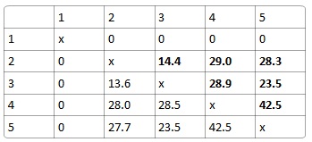
I'm having trouble with my algebra...

Here are the readings on the resistances between my five pins... I can't seem to get the numbers to add up?

Pins Resistance.jpg

Am I just having mathematical difficulties or do my values simply not add up?

Re: getting to know your read/write heads

by guest » Sat Oct 15, 2011 04:11 UTC
those dont add up
but im not sure why

your chart shows pin 1 shorted to all the rest of the pins
which would mean that all the pins should be shorted

what range is your multimeter set to
are those kilohms by any chance

Re: getting to know your read/write heads

by mitcho » Tue Oct 25, 2011 14:09 UTC
What analog multiplexer did you use? I'm using two of these http://ics.nxp.com/products/hef/datasheet/hef4053b.pdf, but I'd like to know your choice. Thanks!

Re: getting to know your read/write heads

by mcanulty » Mon Dec 19, 2011 10:13 UTC
4053 sounds about right, I think I also used a 4051 in there somewhere. They seem to do the job pretty well!

Re: getting to know your read/write heads

by mitcho » Mon Dec 19, 2011 21:06 UTC
@mcanulty: do you have the schematic of the continuous FDD delay (the one you have in the video with 3 FDD)? I'd like to know the logic behind. When one FDD is erasing or recording or playing?

Re: getting to know your read/write heads

by mitcho » Wed Jan 04, 2012 13:26 UTC
Is it essential to erase the floppy disc before writing again anything on it?

Re: getting to know your read/write heads

by guest » Wed Jan 04, 2012 19:37 UTC
you dont need to erase
but you will have a bit of the sound left over
if you do not erase beforehand

Re: getting to know your read/write heads

by jeffctown » Sun Aug 31, 2014 23:38 UTC
I'm working on getting this floppy disk / delay setup going. I have my floppy / arduino setup working as intended and I am able to move the motors and the read write head. I am now working on connecting to the read / write heads and have all of that soldered together but I am not able to hear any output after I write to the floppy disk. I am only using a MP3 player to do the recording (1/8" to the read write head) and I am not sure if this will be loud enough to save audio to the disk (I saw someone mention amplification). I am connecting my floppy drive to a small speaker to listen to feedback but I am not hearing a thing. Do you need to set the WRITE ENABLE on the floppy drive itself once you unconnect and resolder the read / write heads? Do I need to add preamps in my setup?

Re: getting to know your read/write heads

by guest » Mon Sep 01, 2014 19:43 UTC
you will need a preamp to listen to the heads. you can use an old tape deck's preamp just by desolderings its head and soldering to yours.